CK5
Register an account today to become a member! Once signed in, you'll be able to participate on this site by adding your own topics and posts, as well as connect with other members.

The Story Of A Cummins Suburban (Lots Of Pics)

Nice work my man.... About the intercooler... I was told it was not possible, you seem to have that one figured out!!

P.S. Leland's MIG looks like it is keeping him and his imagination well occupied
 
I got a little more done here this weekend. I have been working on the intercooler tubes off and on for awhile and finally got the fitted. They worked out pretty good as I was able to re-route and re-engineer them to fit where they need to be. I cut some out here to bring this up or over or down and I used the chunk I cut out to lengthen this piece or drop that part down etc. When the sparks settled I ended up with about 3/4" of tube left over.

Passenger side tube:

full


A different angle:

full


The way the Banks kit was set up, it used a hose that ran from the intake plenum, ran across the top of the motor, across the exhaust manifold, past the turbo to the wastegate actuator (the thing with the green cap on the end of the hose nipple). I did not really care for the aesthetics of that. The pressure is the same after the turbo and before the intake manifold anywhere in the system, so I decided to make the plumbing a bit cleaner. I installed the passenger side tube and reached around to the back and found a spot that could not be seen from the front of the vehicle. I pulled the tube back out and put a dot on it. I then bored a .187 hole in the tube and took a hose nipple I made out of a piece of .187 brake line that I put a bubble flare on the end of and silver soldered it into the intercooler tube. Now, a hose can be run off of that nipple around the back of the I/C tube and loop up and around to the wastegate actuator. Instead of the hose hanging out in front of GOD and everybody, it will just kind of show up from out of nowhere and loop around to its final destination. About one foot of hose versus about four feet.

Like this:

full


The driver's side was quite the pain in my hinder. I think every straight section of the pipe had to be modified. After all the work that went into it I think it looks pretty good. In the bottom of the pic the infernal power steering lines can be seen. The chunk of bulk hose running kind of parallel to the I/C tube is power steering fluid return to the pump from the cooler that needs final routing and to be trimmed to length.

full


I built my hydroboost and installed it awhile back, but there was no photographic proof of it. I was going to use a H/B off of a late 80's V3500, but the mounting plate was so gangly I did not like how it looked and was not enthused about the amount of work needed to make it fit. I had another H/B off of a '99 C3500. This is the way to go. It has an extremely simple mounting plate that lends itself well to modification. I inverted the mounting plate and bored two holes in it and that was it--done. I had to enlarge the hole in the firewall a few thousandths to get the nut that holds the H/B unit to the plate to fit through the hole and I lengthened the input rod a bit. I used some fluid lines for a mid 90's C3500HD with a 5.7L. They were NOT a bolt on deal, but they required the least amount of modification to fit (the least amount, but still a lot). I liked them a lot because they come off the H/B unit on the engine side of the unit instead of the fender side like the V Series hoses. This gave me room for my clutch master cylinder which is also visible in the pic. Obviously it is in, but I do not have a couple key pictures to illustrate the work done and it would take too much to try to explain what I did, so I am going to hold off describing that whole deal until I get a few pics of a couple parts.

full
 
Last edited:
That is going to be so nice! I put hydroboost and a hydraulic clutch from an 89 old body style 1 ton into my 69 K20 - your going to really like the h/b!
 
Well, I snuck out for a couple hours this weekend and got a couple things done. Actually, I got nothing done. I bolted a few parts on and stared at them, but that is progress, right??

Anyways, from a previous post this pic might look familiar:

full


The situation is, even with removing the flared portion of the frame rail, the water inlet was still obstructed by the frame rail. Another issue present with this setup was A/C compressor clearance. Most people who put a Cummins in a GM frame need to notch the upper portion of the frame rail for compressor clearance. I have the motor set so low that I was going to have to notch the LOWER portion of the rail. I did not think that would be so cool having the compressor free-balling it down below the frame and coupled with the water inlet fitting issue I decided something else was needed. This is what I ended up with:

full


I'm not sure of an application. It *might* be off of a Kenworth chassis, but I do not know for sure. It is brand new, but got moist during an event where water was falling out of the sky and it developed the reddish coating on it--I think it might be called rust and the cause of it might be called rain--not sure though ;-). Anyways, it has a separate fitting that mounts onto it for the water inlet. This is great except a fitting is not made that will work for my application--no surprise there. I have my flange made and it is mounted on the housing. I am going to make the nipple for it out of a piece of heavy wall, mandrel bent exhaust tubing to clear the frame rail. The top of the housing will mount a bracket for the bottom of the alternator. This unit mounts the A/C compressor directly above the water inlet fitting up and away from any frame rail interference. Of course with this I needed yet ANOTHER different water outlet fitting (thermostat housing)--I think this is number four. The machined flange on the water outlet fitting will not be used. It looks just like this:

full


Part of the reason for needing another different water outlet was because a bracket for the top of the alternator was needed. It looks like this:

full


It is going to get a slight modification later on for reasons relating to lack of space for another part, but that is s story for another day. Now, with all of this, I get to use a different alternator. I decided to go with a nice hefty medium duty truck unit. Dodge alternator on right, MD truck is on left--slight size difference:

full


Here it is mocked up:

full


I just went over to Russ's (BadDog) house this afternoon and picked up a part he machined for the lower mount. Cummins makes what I need, but I ordered one several months ago and still have not received it. I guess they are still doing a survey to see if there is iron ore where they want to start mining. Then they will have to start the mining operation, process the ore, get it to a steel mill to be made into a part that I ordered. That being the case, I decided I will make one myself. I also dropped off some raw materials while I was there for him to machine into something REALLY cool that is going to help me deal with another issue that pooped up, but, once again, that is a story for another day.

I was a bit nervous about clearance for an accumulator to fit near the intercooler tube, so I dug out one that I had here and did a test fit:

full


By the looks of it, I am guessing my eyes were in calibration when I laid it out because it looks like it will fit good. The pic does not illustrate it too well, but there is a decent amount of clearance all the way around it.
 
Last edited:
Well, after doing some work on the steering shaft in my wife's truck this morning, I decided to try my luck at doing something on the Suburban. Almost immediately it resulted in a pretty good display of blood-letting. It wasn't bad enough that my right index finger knuckle somehow touched a surfacer disc on a grinder that was spinning down and made a 1/8" x 3/16 hole in said knuckle, but while retrieving the bandages from my work bag, I managed to completely open up a wound I created on Thursday with a hammer and drift on my left index finger resulting in significantly more blood than the initial injury created. I was a bit aggravated at this point. I decided to press on and see if I could keep it together enough to get something done. Perseverance prevailed and I successfully accomplished something.

I decided the fun-for-the-day would be the lower alternator bracket that I ordered months ago from Cummins and am still waiting for.
I started with this:

full


I took a piece of 1/2" plate and cut a piece to fit the top of the water inlet housing mounting to the two rear holes (front hole not used). Then I took a piece of 3/8" plate to make legs that look similar to this:

full


The legs will go between the 1/2" plate and the 1" round bar that Russ (BadDog) bored a .500" through-hole for me. I welded it all together and ended up with this:

full


It turned out good. Mounted up and gave some more girth to an already fairly stout upper bracket. While I was doing this, I got a call from Russ and was informed that he had finished machining an uber cool part that I dreamed up to solve a problem that arose in an area near this. I will post details and pics after I get over to his place and acquire the part. Stay tuned.
 
Last edited:
looooking good mang. Cani throw something out there for you........

that air line to the wastegate. do you still have intake manifold air (boost) going to the AFC housing on the injection pump from somewhere else? that line on the driveside might have been feeding the AFC control for the IP. you're going to definately want AFC control for smoke control. most wastegates take pressure from a fitting directly on the compressor housing. usually the boss closest to the outlet. you just tap for a 1/8" FNPT in there, and install a brass 90* most turbos come factory oriented like that. makes it one tidy self contained unit.


like the hose there will go to a fitting tapped into the boss on either side of the id plate.

Truckstuff004.jpg


Twins004.jpg


...Oh and BTW I had to cut my inner fenders for the IC piping on mine.
 
Yeah, the plumbing from the intake to the IP is still there. Cummins did that in a real clean manner compared to what Banks created. The way I have my wastegate plumbed the hose will appear from out of nowhere and loop right on to the actuator. Looks pretty clean--much cleaner than it did previously.
 
Is that one of those altenators that came up missing from a freightliner dealership in colorado and magically reappeared in your garage but in slightly reburbed form?
Amazing how you get married...have kids...and then suddenly 3 or 4 years later you wander out in the shop and look at that pile of parts and say....oh ya...i was gonna do something...no where was i...
I have finally realized that the fleet i aquired is going to have to be axed down to a select few and add one more. I need a back up work truck and so far i have two printed pics on my door in the shack out here to see which one grows on me first...or the most. Its either going to be a M1010...or a M1031....in desert tan of course. I'll save coin from selling off the heard...keep the 79 and maybe the 79 2wd and axe the rest to include dare i say it the chalet. of course with the heard thined from 8 to 2 then add one...is alot more managable than 8 is to much.
Lookin good btw...one lil step at a time....and countless years later will only make the first rumble that much more sweeter....
I see the cac tubes and such are a bit tight...and uber engineering a strong
piece of flat stiff flat plate with gussetts times two on the pass side to help hold the cac tube from moving slighly as it psi's up and down with a couple big ole rubber lined odell clamps might be an idea.

Love the CAC itself...thinkin it might work as well for a 73-91 core support as well....

Just got back to the rig after my 24 hrs. off....and guess who decided to drop in tomorrow...Bob....Beth and her two wonderful kids (member the one you called evil?)

DW
 
Is that one of those altenators that came up missing from a freightliner dealership in colorado and magically reappeared in your garage but in slightly reburbed form?

Actually, no. I was going to use one of those and I picked the nicer looking one and decided to clean out the "big truck funk" that was plugging up the internals and when I got it disassembled I found a broken part in the rectifier area. The other one was a low amp unit and looked rougher than the first one, so I got in contact with a pal at a big truck supplier in town and got a very nice deal on a brand new 130A Leece-Neville. I used one of the other ones for the mock-up and when I was welding nearby.


Amazing how you get married...have kids...and then suddenly 3 or 4 years later you wander out in the shop and look at that pile of parts and say....oh ya...i was gonna do something...no where was i...

I have no idea what you are talking about. Wait, actually I understand completely--you have not seen my garage lately.


I have finally realized that the fleet i aquired is going to have to be axed down to a select few and add one more. I need a back up work truck and so far i have two printed pics on my door in the shack out here to see which one grows on me first...or the most. Its either going to be a M1010...or a M1031....in desert tan of course. I'll save coin from selling off the heard...keep the 79 and maybe the 79 2wd and axe the rest to include dare i say it the chalet. of course with the heard thined from 8 to 2 then add one...is alot more managable than 8 is to much.

Hmmmmm....... Imma send you an email on this one......


Lookin good btw...one lil step at a time....and countless years later will only make the first rumble that much more sweeter....
I see the cac tubes and such are a bit tight...and uber engineering a strong
piece of flat stiff flat plate with gussetts times two on the pass side to help hold the cac tube from moving slighly as it psi's up and down with a couple big ole rubber lined odell clamps might be an idea.

Actually they fit pretty good and have decent clearance. The pics make them look tighter than they are. I can't seem to figure out an angle to make them look in a pic like they look in real time.

Love the CAC itself...thinkin it might work as well for a 73-91 core support as well....

Actually on a '73-'91, you could use a stock 94+ Dodge unit as you would not have to go under the hood latch like I do on the earlier body. Probably be able to use the entire cool pack from a Dodge donor.


Just got back to the rig after my 24 hrs. off....and guess who decided to drop in tomorrow...Bob....Beth and her two wonderful kids (member the one you called evil?)

DW

Uh, can't say as I do, but if I did it must have been a bad one.... Bob is nice though.
 
Well, I determined a problem that I knew existed was more of an issue than I initially believed. The stock fan from the Cummins has a couple bent blades. Now, they are not bent horribly, but I am not too excited about straightening a fan blade. I did a bunch of research and learned a few things. The first thing I learned was that these fans were known for pitching blades off at speed--not good, but even worse when the stock viscous clutch is replaced with a direct drive clutch that has no "cushion" to speed up. The clutch engages and it is at speed right now. This is not a good mix with a fan known to pitch blades.
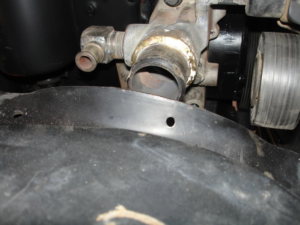
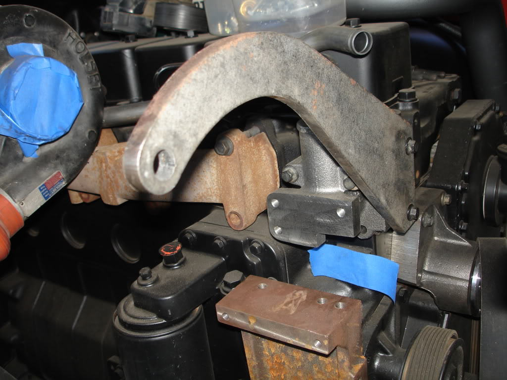
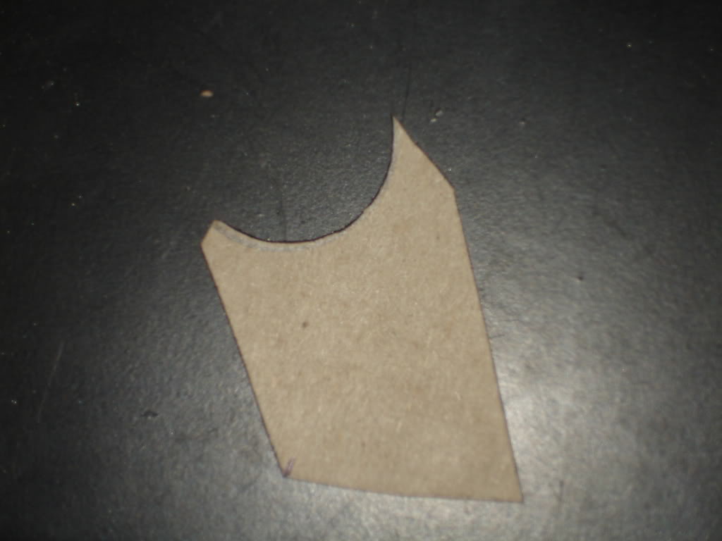
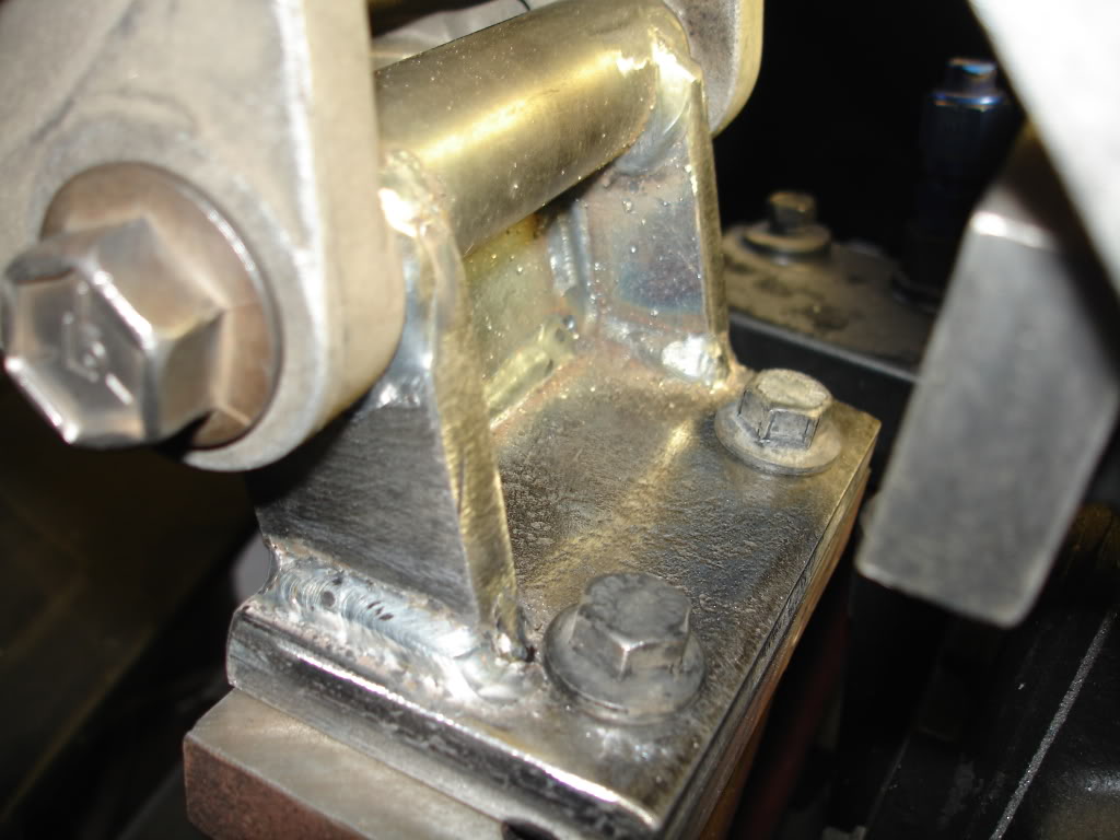
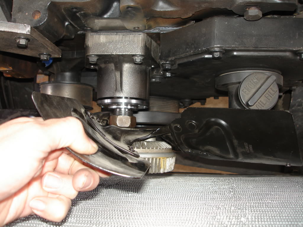
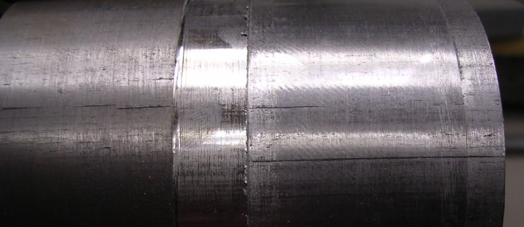
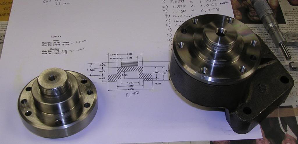
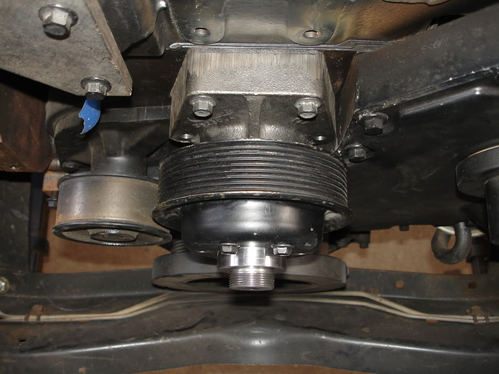
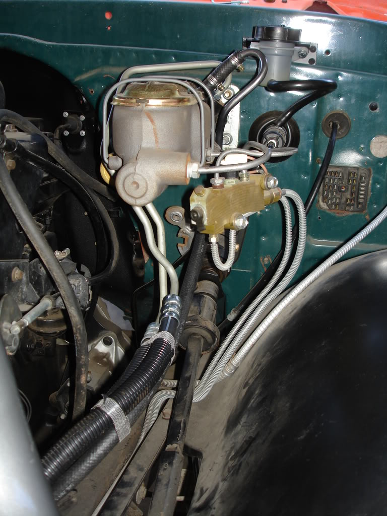
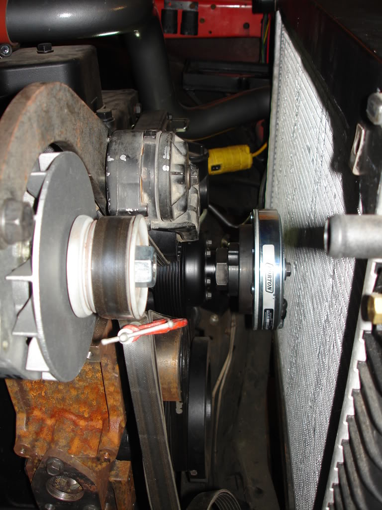
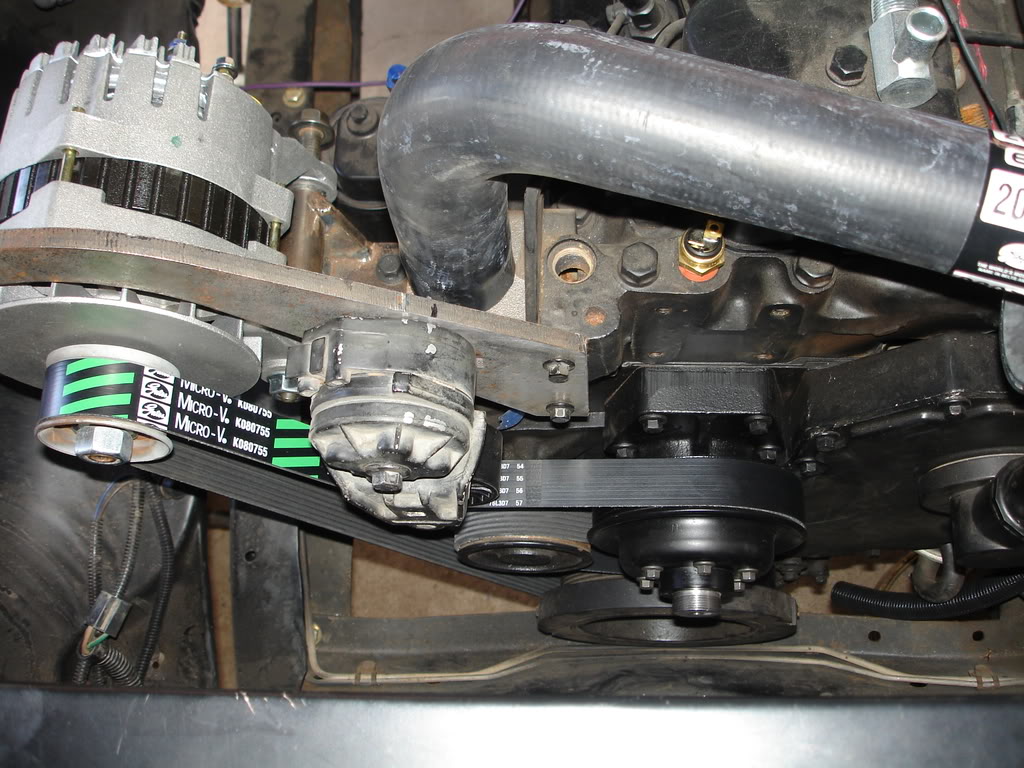
The next thing I learned is that this fan is not correct for the fan hub I am using. A few posts back there are pics of the differences in the fan hubs. The main difference is the length of the hubs. The offset one sticks out further than the non-offset one. The fan I have is designed for the longer hub which creates a fitment issue when run on a short hub. This pic illustrates what I was going to do until I realized my problems were more severe than I initially thought:

full


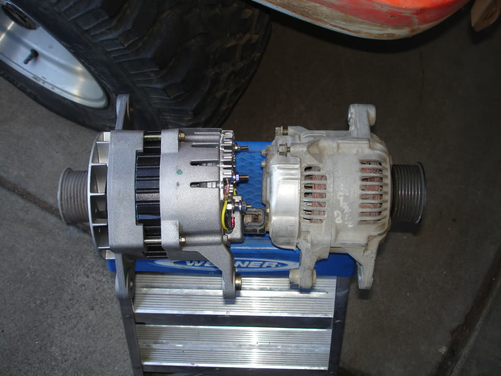
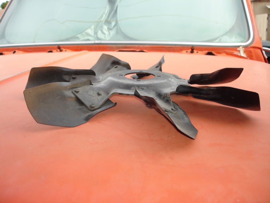
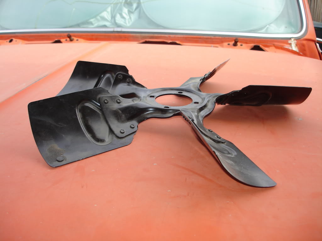
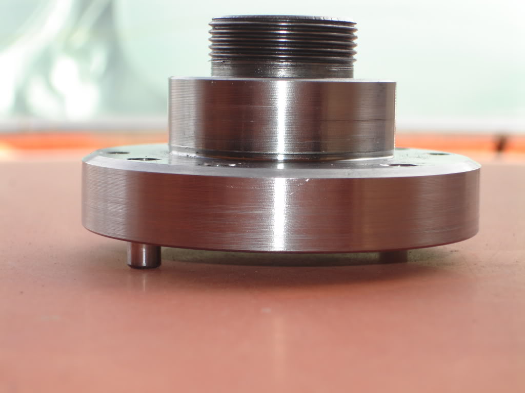
In the pic it is just barely visible, but the clutch is not threaded completely on to the hub. This is for clearance between the fan and crank pulley. I thought it would be ok because it did not hit and the fan would, in theory, pull away from the engine toward the radiator when engaged. Then I learned how crappy the fan was stock among other things and decided something else needed to be done with it. The stock fan itself is a rather weak fan compared to others I have used in the past which did not thrill me, but what could I do?? The fan is a strange animal. Here are a couple pics to illustrate the strangeness:

full


Not too strange looking, right?? Well, flip it over it gets stranger:

full


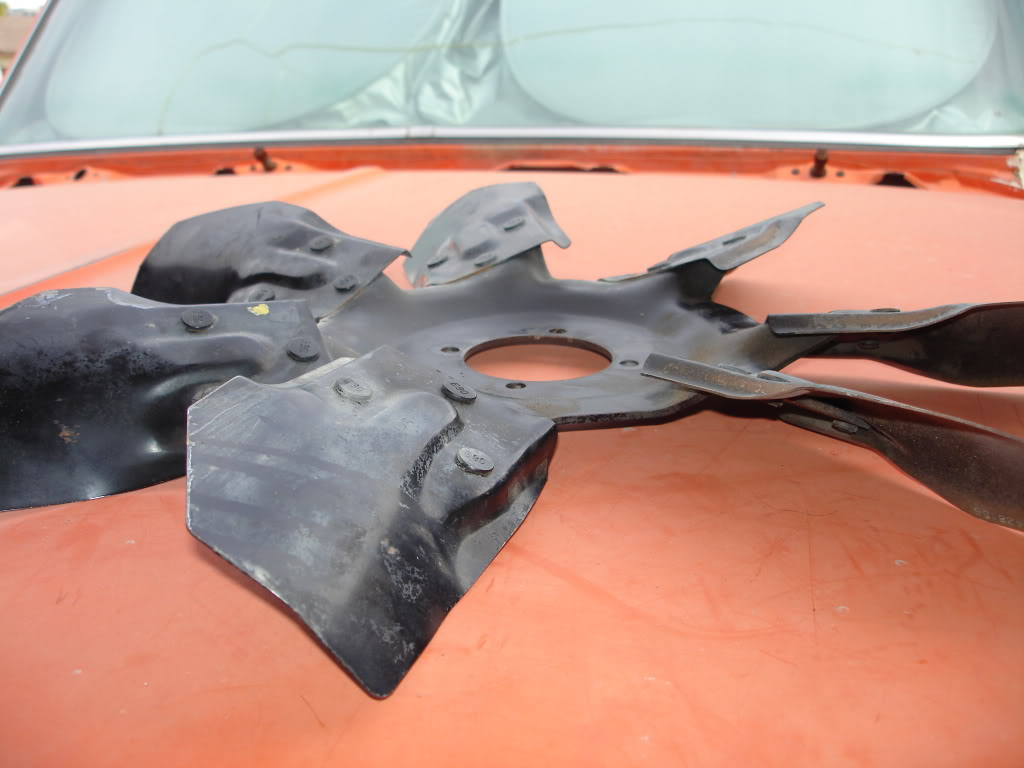
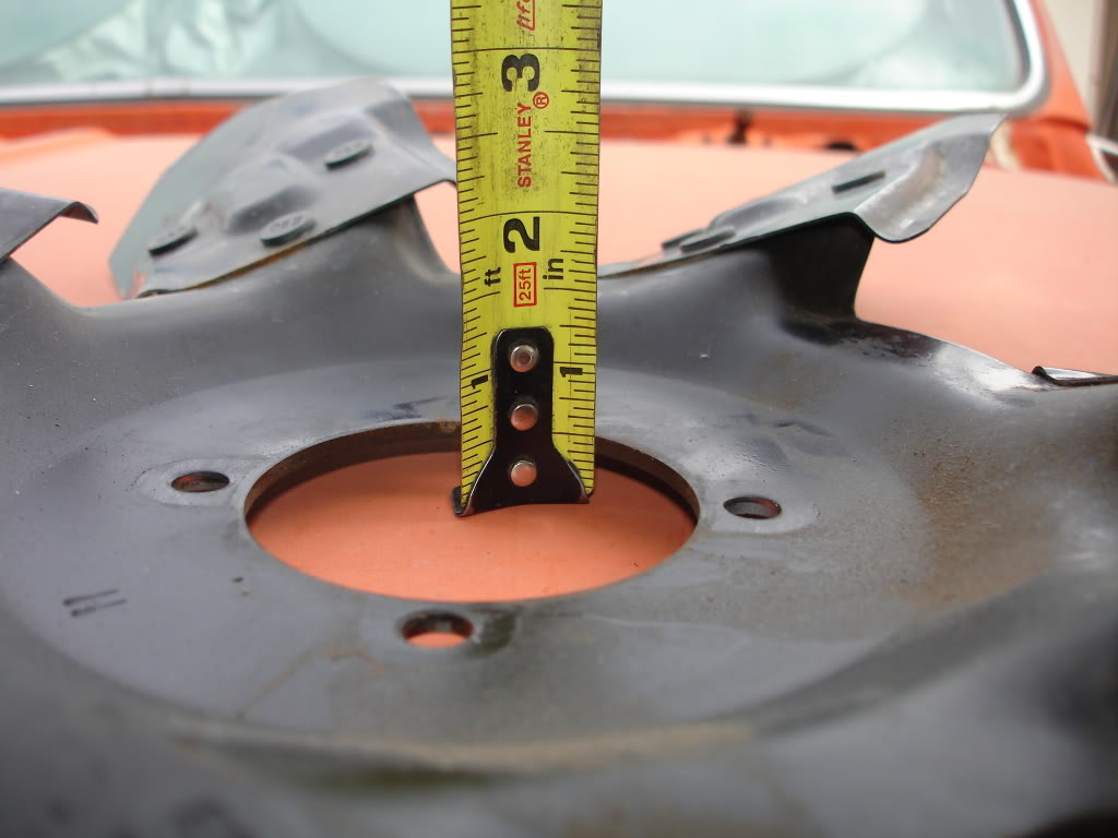
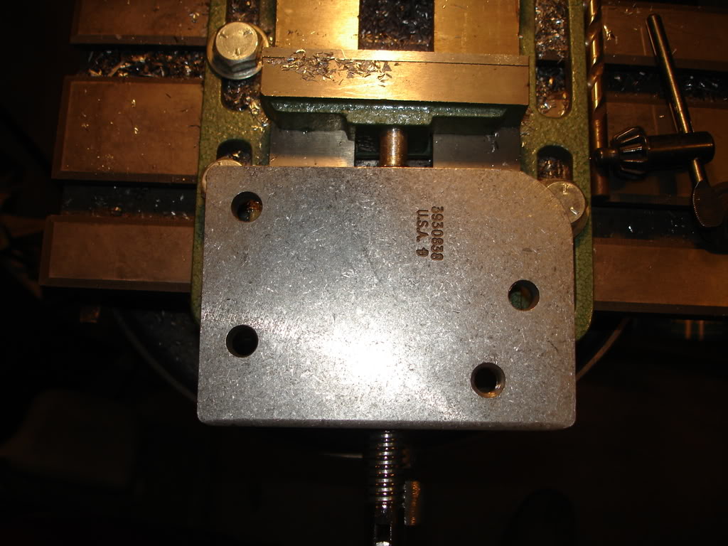
Add a tape measure and it gets real weird:

full


Yes, that is about 3/8" of backspacing on that blade. This may be typical of an inline motor, but as a purveyor of V-configuration motors it is real weird to me. Now, to use a stock blade I would have to find one that has LESS than 3/8" on the backside. Hmmm, does not sound like fun. I got no help from Dodge on what fan I could use because there were a bunch of variables. This motor, originally being non-intercooled, got a smaller diameter fan than the intercooled motors. That coupled with the using of the different hub got me nowhere. So, what to do?? I had one of the super-bitchin' big block fans (the one that the big seven blade fans from the 70's supersedes to because it pulls so much more air) from the previous motor, but the backspacing on it was tremendous compared to the stock Cummins fan. That's not going to work--or is it?? Hmmm.

full


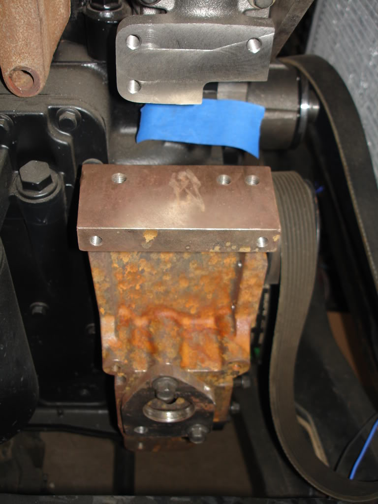
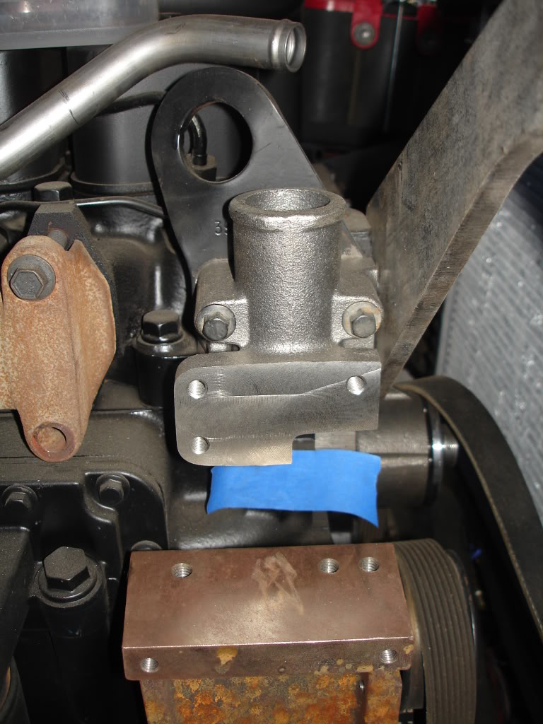
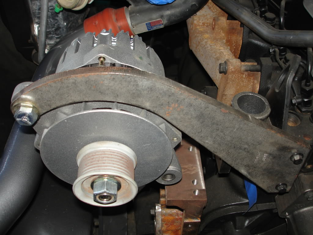
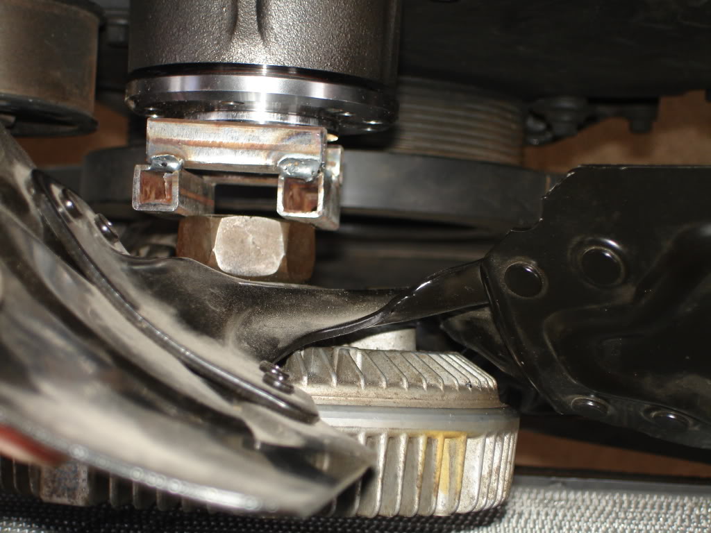
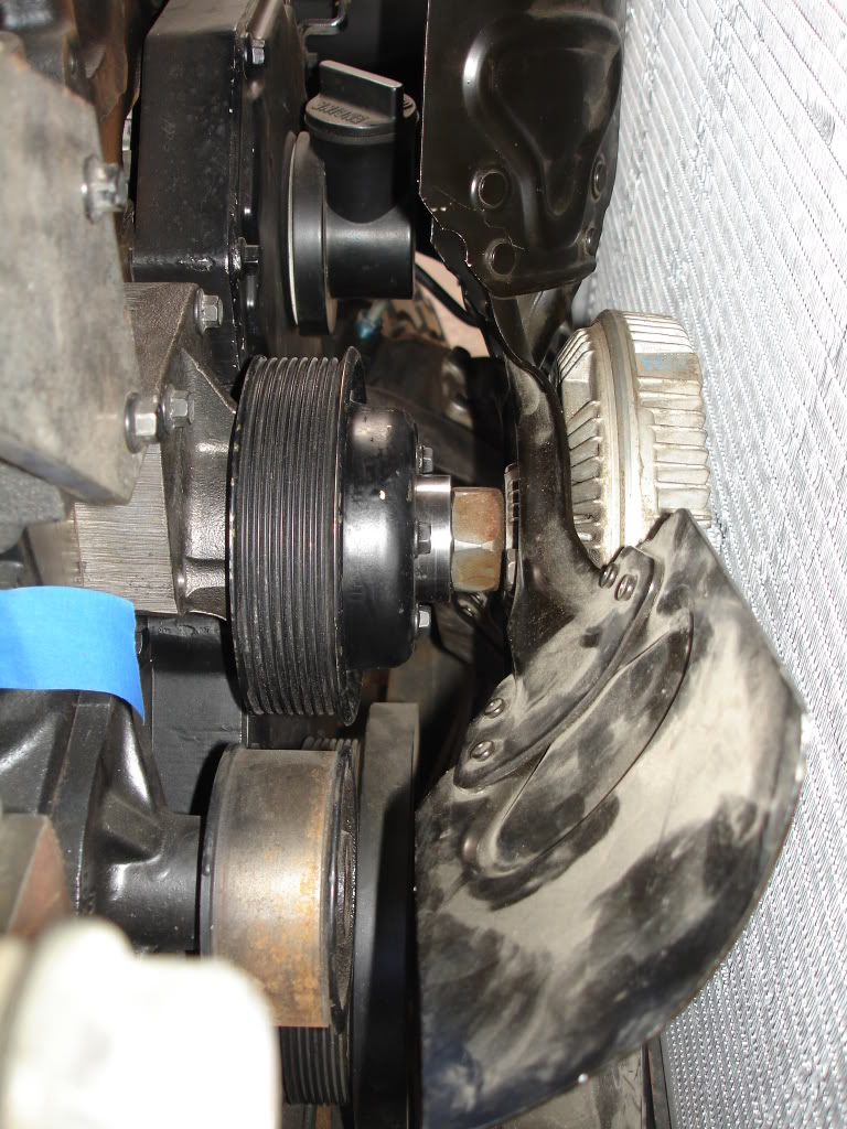
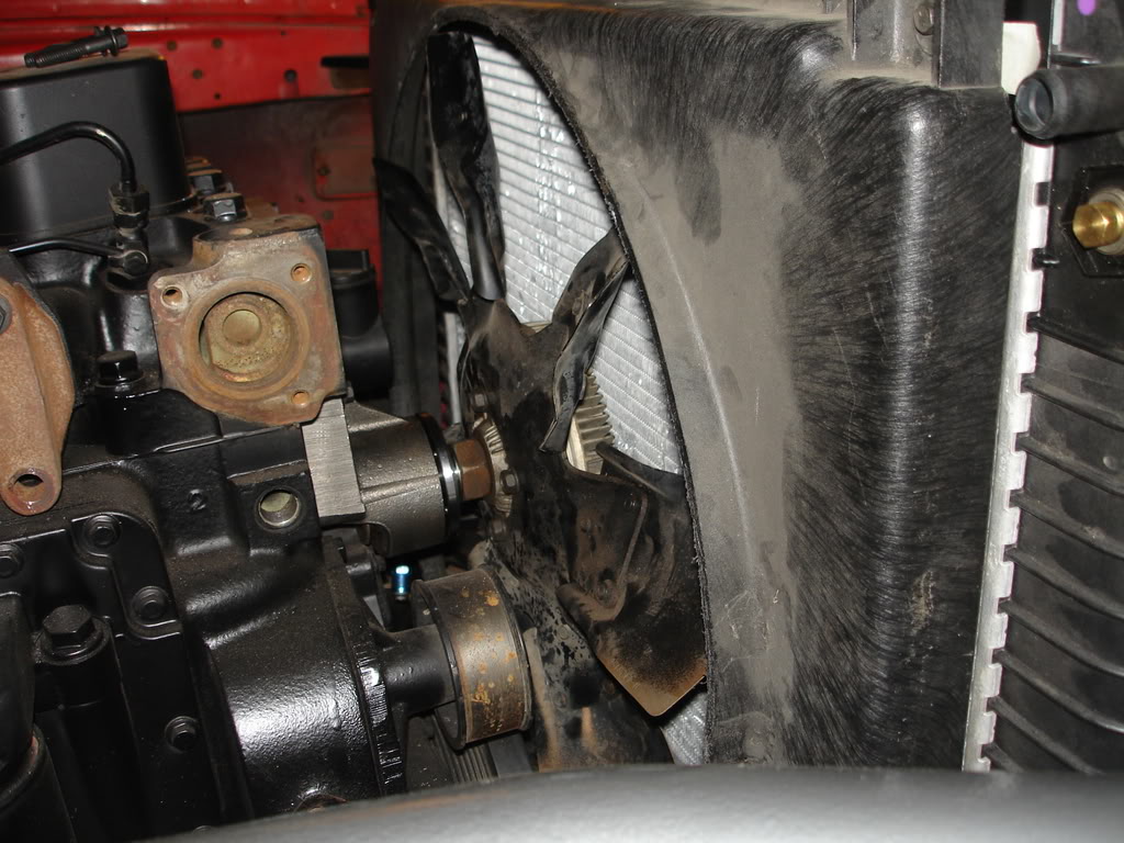
Man, that's a lot of backspacing. Probably can't be done so I think I'll give it a shot. Let's see here. May as well try a test fit:

full


Yup, just as I thought--it hits everything. Oil fill tube, water pump pulley and crank pulley. Not good. Well, what if it could be spaced out a bit. By my measurements it would take a fuzz under one inch. Hmmm, how to make a temporary one inch spacer to test my theory??

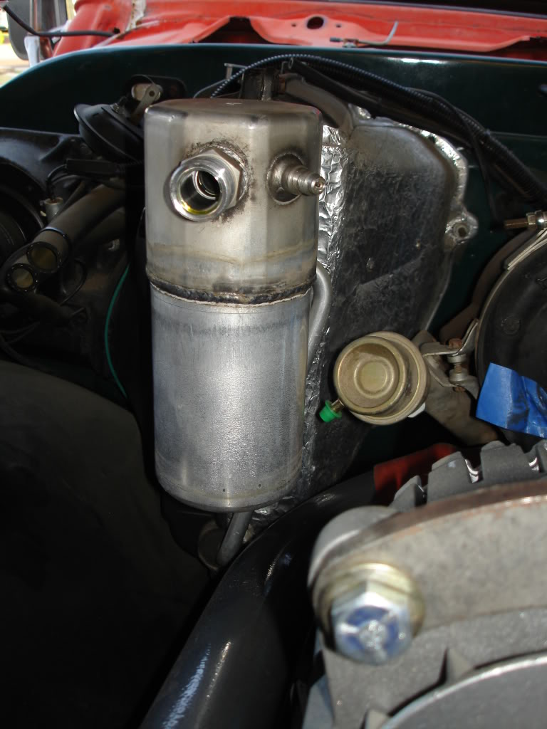
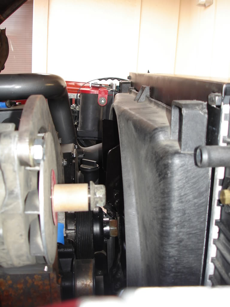
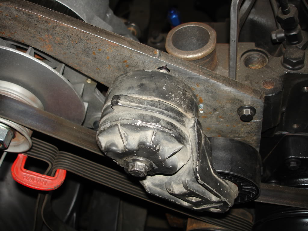
A couple pieces of half inch square tubing cribbed should suffice:

full


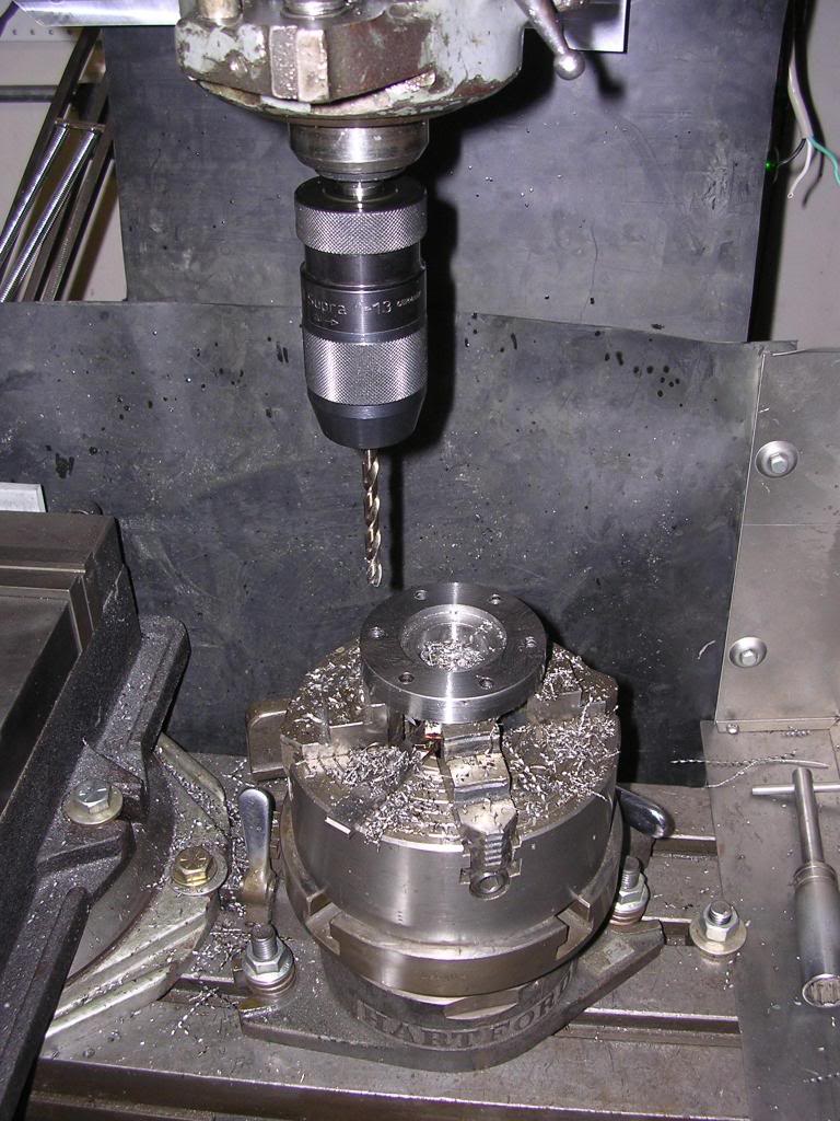
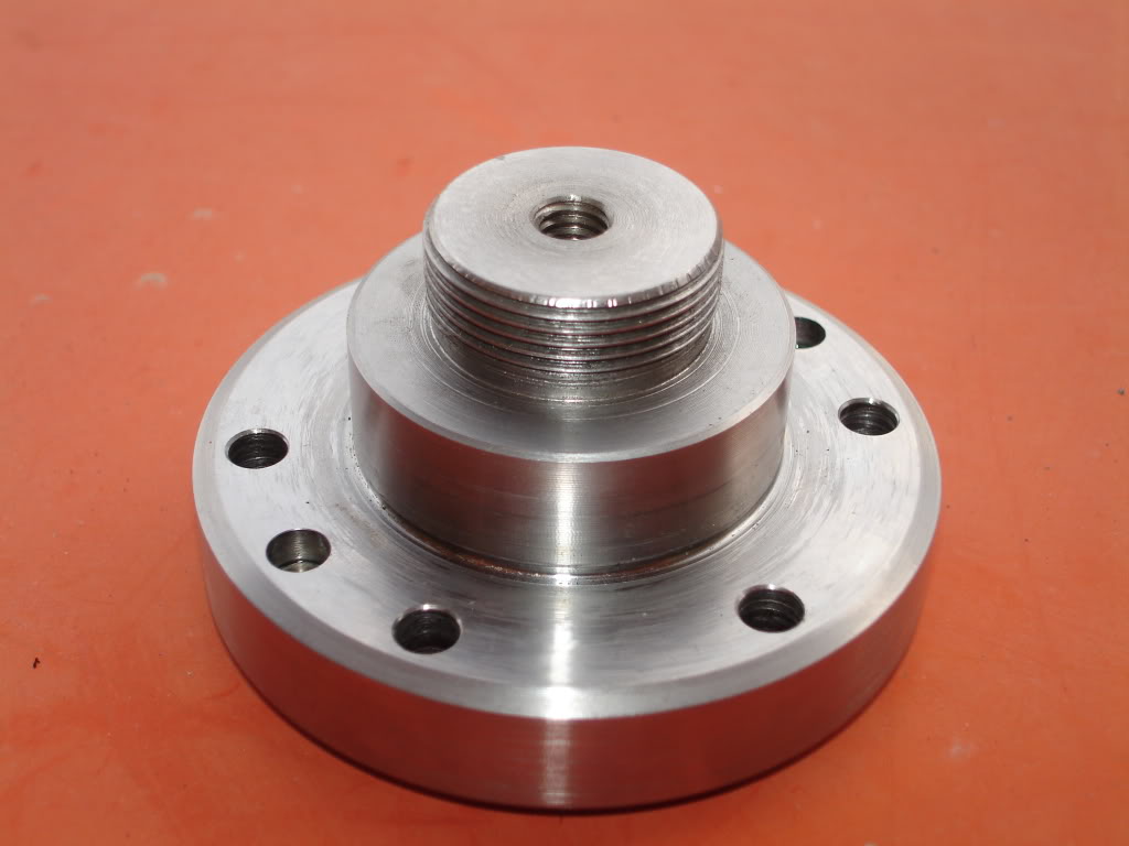
Wow, it clears everything nicely. Maybe I am on to something. Now what do I do about making something a bit more permanent than the stacked tubing. I consulted my personal machinist Russ (BadDog). He thought it sounded easy enough and agreed to give it a shot. I went over to his shop with a round slug of metal that i have had for years, a fan hub, a couple pulleys and one dimension--one inch out from the fan mounting surface. Well, it turns out that my slug was crap. It had terrible cracks in it just under the surface and would not clean up.

full


A new slug will need to be located.
 
Last edited:
Ok, so where to get a slug that will be of decent enough quality to machine what I am envisioning?? Russ @BadDog has a friend with a machine shop that has bins of drops (cutoffs) and said he was going down there to get something and he would check to see what he had that we might be able to use. He found an unmarked slug in a bin of 4140 and 4142 drops, so it should be one or the other which would machine easily, but have good strength. Well, it turns out to be something completely different. Russ found this out after beginning the machining process. The material coming off of the slug was like a coiled up razor blade and would not break!! After some investigation, he determined that it is annealed 4340 spring steel. Way overkill for what we need, but it's what we have. He managed to find a feed setting that would break the material coming off into about 4-5 inch pieces (he was getting 4-5 FOOT long pieces of razor blades coming off of it). The material composition did not lend itself well to a nice surface, but it isn't going to be seen, so I don't care. This is what we ended up with: (no pics of it being machined, but here is one of the bolt circle being drilled)

full


If you look closely at this pic, you can see the one dimension I gave him to start with (one inch):

full


The threads are 30mm 1.5 left hand threads. They turned out better than the ones on the stock hub. This pic shows the 1/4" hardened pins that Russ added for more insurance in alignment and strength:

full


Another angle:

full


We decided to go with the pulley for the long hub so the spacer could mount directly to the hub and have a nice shoulder for strength. Here is a test fit on the motor:

full


Looks sweet. Let's try the fan now:

full


It fits good with good clearance to the radiator (pic does not show this well) and 3/16-1/4" between the fan and the oil fill, water pump and crank pulley. Now for a shroud:

full


It fits good. Not quite half-in half-out, But I'm calling it good enough at this point. I did all of my test fitting with the stock viscous clutch because it is less cumbersome that the Horton that has a leash (Harness) that seems to always be in the way when working with it. The clearance between the clutch and the radiator is great enough that it will clear the Horton fine.

So there you have it. One bitchin' piece of engineering to solve a strange problem. Many thanks go out to Russ for his perseverance and skill in turning an otherwise generic slug of metal into spiral razor blades and a hub that alleviates a major roadblock on my path. Thanks again!!
 
Last edited:
Nice! It's fun to see people machine their way out of a tough situation...
 
I've got a buddy who can make parts, my jaw always drops when I see people making a part to take care of an issue. Just pretty cool to see that kind of talent in action.
 
I've got a buddy who can make parts, my jaw always drops when I see people making a part to take care of an issue. Just pretty cool to see that kind of talent in action.

Yeah, it is pretty cool. If I had his skill and equipment I would have created exactly what he made, but I don't, so I have to be content explaining what I need and then wait for him to turn my idea into a physical part. The great part is that he is a perfectionist, so I never have to concern myself with any aspect of his work. If he gives it to me, I know it is ready to run and is held to tolerances that are way tighter than would be deemed necessary for an automotive component. It doesn't get any better than that.

I have to stay up real late tonight, so I figured I'd go out in the shop and get something accomplished. I did not know what, so I decided to think outside the engine compartment for a change. Fuel lines, that will be the project for tonight, err, this morning. I was hoping to be able to use what is on the truck for fuel lines, but they run down the right frame rail and the fittings are on the left side of the Cummins. I could not devise a non-hack approach to get the fuel from one side of the frame to the other so, as usual, I had to make something different.

I started with the rear lines. The only specs I have to go by are the diameters of the connections on the motor. The lift pump uses a 5/16" hose barb and the return line uses a 1/4" nipple. My tank is set up for 3/8" line, so I decided to make the feed line 3/8" instead of 5/16". Now, I am no pro at bending steel line, but I have learned a few things over the years. I recently upgraded my equipment from a POS Snap-On tubing bender that did 1/4", 5/16" and 3/8" tubing in one tool that was absolutely horrible for anything over 1/4" because the handles are too short, and went to four different Ridgid benders. Man, what a difference that made. Another thing I learned long ago is that one line is simple to make, but making a second line match the first line requires some skill--which I do not have much of. I realized that, lacking this skill, I should start with the larger diameter tubing and match the smaller tubing to it. This made my life much easier as the smaller tubing is much easier to manipulate to match the larger diameter. It took me a couple hours and probably would have taken someone with bending skills about half an hour to forty-five minutes, but hey, time is cheap in the middle of the night.

Anyways, here is what I ended up with: Rear lines (there are two stacked on top of each other)

full


The variances in the ends are for hose clearance to each other. I am running them in factory type clamps that hold both lines tight together, so at the end the lines they have to splay out or at least take a different angle so that a hose and clamp can go on each one without interfering with the other.

The front lines:

full


All lines together:

full
 
Last edited:
Run the lines across the transmission crossmember that way they get to the correct side and they are protected by the crossmember.
 
good progress bro! I keep on wanting to give you a buzz, but I am unsure of when you are asleep or at work? Nice lines though and the fan hub thingermajig came out sweet! keep up the good work
 
I am working days this week and I will be around all day tomorrow, er, uh, today 12/28.

I have actually been making some progress on this, but I haven't loaded the pics etc, so here are a couple pics for now.

I got my power steering lines done!!

full


I know there are a couple people here who have been waiting to see this thing get wired, so here is the start of it. This is the big block harness that I made, grouped in circuits, awaiting routing and fitment.

full


Those of you who know my stash of GM electrical components will understand when I say that I am waiting on a large box of electrical stuff that I plan on working on this harness once. And nevermore......
 
Last edited:
On with the progress.....

I figured it was about time to get a belt on this thing. The sticking point that I was dealing with was the tensioner. The water inlet housing that I used has provisions to mount a tensioner bracket on it in one of two locations. One is down low (there are two bolts in the lower holes in this pic) and one upper (you can just make out some silver spots in the pic where the upper mounting location is).

full


This plate is used to mount the tensioner to the water inlet housing: 3/8" plate

full


The problem with this setup is the location of the mounting holes in the inlet housing. The upper holes are directly in front of where the compressor will mount. This is bad. The lower holes put the bracket and plate into the frame rail. This is bad also. A plan "C" is going to be necessary. After staring at it for a few hours, I got an idea. The upper alternator bracket is a nice stout piece of 3/8" plate. Hmmm, that is the same as the tensioner bracket....

full


So I decided to route a belt on it and see if my theory would fly. I grabbed an old belt I had from a 4.3L and routed it around and used a clamp to make it the correct length. It looked like it should work, so I went ahead and drilled and tapped the hole in the plate to mount the tensioner. I did not drill the hole for the indexing pin yet.

full


It looks like it should work.

full


Now, it is hard to tell from the pic, but the routing of the belt was not ideal. It came straight up off of the crank to the fan hub, went around that, under the tensioner, around the alternator, down around the water pump and then back to the crank. I got a couple belts this length, but before I even tried them, I decided this was not a good setup. The fan hub had only about 90* coverage. When that Horton fan clutch engages, the belt is going to scream like a scalded ape. I decided to re-route the belt (I'm glad I made this decision before I bored the hole for the indexing pin on the tensioner). Now, the belt comes off the crank and goes to the water pump, wraps around it (over 180* coverage), then goes over to the fan hub and wraps around it (well over 180* coverage), then under the tensioner, around the alternator and back down to the crank. So with this change, I got excellent coverage on all the high-drag components without resorting to adding pulleys etc.

This is what I ended up with:

full


I was concerned with the location of the indexing hole for the tensioner, but in the end I got it right on the money. With the tensioner pulled all the way back, a belt can JUST be slipped on and when relaxed the tensioner is at 3/4 of its range.

With that done, I started looking in my box of stuff left to put on. Unfortunately, my box appears to have more stuff in it than there is room left under the hood for it. I decided to tackle the horns. They are Delco replacement horns, but they look like something off of a European import. I tested them out and they are loud as hell and have a domestic tone to them (no import squeak horns here). I toyed around with a few mounting locations. I do not recall this thing having horns on it when I got it, so I do not know where they are supposed to be, but I found a place that works well and would otherwise be unused space.

full


I'm getting closer.......
 
Last edited:

Latest Posts

Top Bottom