CK5
Register an account today to become a member! Once signed in, you'll be able to participate on this site by adding your own topics and posts, as well as connect with other members.

Power Window Idea <--- IT WORKS

But how was the window motor drawing current through those points while you were measuring? It sounds like you measured before you put the window wiring there, so what was pulling current while you measured?

I'm not understanding your question.

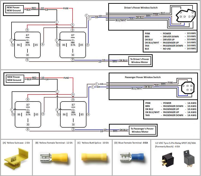
I measured AMP draw on the motor AFTER I had the relay mod done. I used my fluke 375 AMP clamp on the motor wire and then activated the window motor to read the AMP draw of the motor. The motor only draws amps when it is being used obviously. When the motor dead headed (window all the way up or all the way down) is when the reading was 17.2 amps.
 
I was asking about the voltage drop measurements. When there is no current, there is no voltage drop, which made me wonder when you measured it. At 17A, even the main battery cable would show a mV or 2.
 
You will get voltage drop when wiring becomes old and has more resistance. I put my fluke ground lead on the battery negative and the positive lead on the battery positive and measured voltage, next I moved my fluke position e lead to the hot junction block to see what the difference was. If the wiring had too much resistance the voltage would be less than battery voltage.
 
Only if there is current through that portion of the wiring. At 0A, the voltage drop of any reasonable connection (even through a bulb or something) is 0V. With current flowing, the voltage drop is proportional to the resistance of that portion of the wiring and the current.
 
Forgot to update this thread, got both windows done and they work ALOT quicker than before.
 
So I read through this and I have a question can you perform the mod all in the driver door for both doors or do I need to do both doors separately?
 
here's a diagram for those interested...


full


and the headlight mod...

full
 
So I read through this and I have a question can you perform the mod all in the driver door for both doors or do I need to do both doors separately?


each door is separate.
 
Yep. I bought some relays and connectors in bulk (40 count) along with some 10 ga. wire (10 ft sections) some time back. Plan on making my own. I need some serious pick and pull time to see what I can come up with as far as power distribution. I have several sets of lights I need to install also. Ha, I just counted. I have 4 sets! 2 for each 'burb.
 
Here is an updated/simplified wiring diagram overlayed on a factory power window wiring diagram. The only modification you need to do is run new power and ground wires (one each door, connected to both relays with jumper or splices) for the relays and cut into the two wires per door running in between the motor and factory switch.

1727307247226.png
 
Last edited:
Here is an updated/simplified wiring diagram overlayed on a factory power window wiring diagram. The only modification you need to do is run new power and ground wires (one each door, connected to both relays with jumper or splices) for the relays and cut into the two wires per door running in between the motor and factory switch.

View attachment 487244
That's 2 relays per window, correct?
One for up and one for down
 
That's correct. Both relays are tying the motor leads to ground until you flip a window switch. Then one side is pulled to +12V. If both directions are selected at the same time (one at each door), both motor leads are tied to +12V, so you are still fine.

If you did this with a normal "polarity reversing" DPDT relay, you would still need a second relay to turn the motor off, so a pair of the more common SPDT relays works well.
 
I updated the diagram to avoid people vandalizing the door harness and the inevitable failures later on. Use solder sleeves, or solder and heatshrink. Cover the terminals with heatshrink. A relay socket is also a good choice if you use a good one.

1728563922482.png
 
Top Bottom