CK5
Register an account today to become a member! Once signed in, you'll be able to participate on this site by adding your own topics and posts, as well as connect with other members.
Nice hubcaps!


Thanks!

Finally coming around to the "Hershey Kiss" style that belongs on a 1972 anyway.

Next step is finding a post somewhere about how to restore them properly. It seems like when the factory sprayed the black sections they must have used some kind of overlay to mask them... if someone already sells that mask it would save a LOT of tedious taping and masking for each one individually. Also noticed that the black is not a gloss... but is actually more of a satin / flat style black. Kind of like the accent stripes used on Shaker hood scoops from that time period. Will definitely want to play around with it to make sure it looks "stock" when I'm done. Also need to find the original GM color code for the blue used on the bowtie logos to get that "just right" also.

-G
 
Yeah, I like those style caps... I will have a new t-shirt design in a week or so that feature them.
 
2020.04.27 - UPDATE! - MOMENTUM BUILDS....!!


Came up a little short of some parts that were needed for the muffler hanging exercise, but that didn't stop the forward progress.

It was a beautiful sunny day in TX.... it always feels good to roll up the garage doors and let the sunshine in, and enjoy a hot cup of coffee while setting up for the day.

full


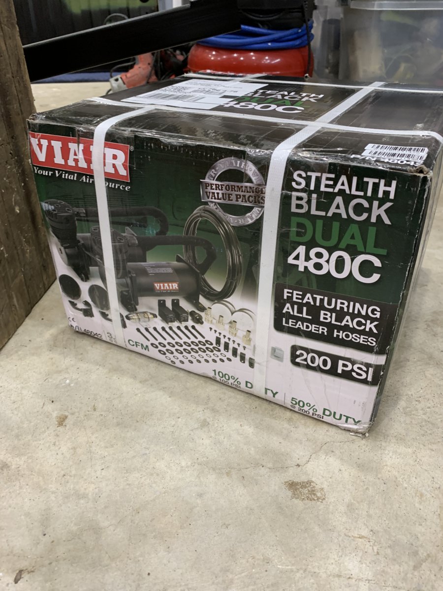
The overall goal lately is to find homes for all the remaining items that need to co-exist under the truck. That includes not only the exhaust system, but also a dual battery setup, dual Viair compressors, a 2 gallon air tank (if possible), rear driveshaft. airlines, brakelines, fuel lines, fuel filters, etc. Each piece that get installed steals space... but also reveals the clearance issues that were not fully appreciated. This was revealed in vivid detail yesterday.

Simple goal was to install the Strange 3rd Member and rear driveshaft to determine clearances with the suspension at full-compression.

full


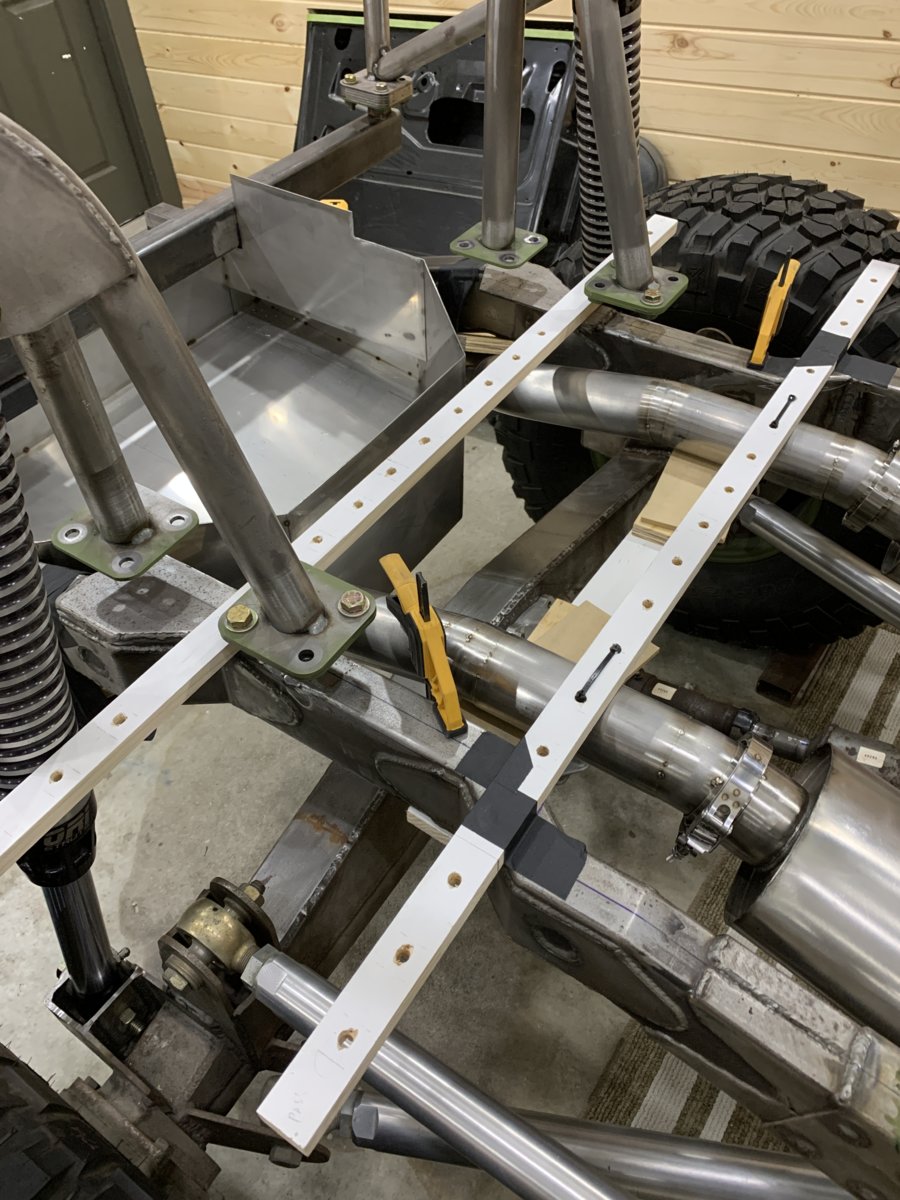
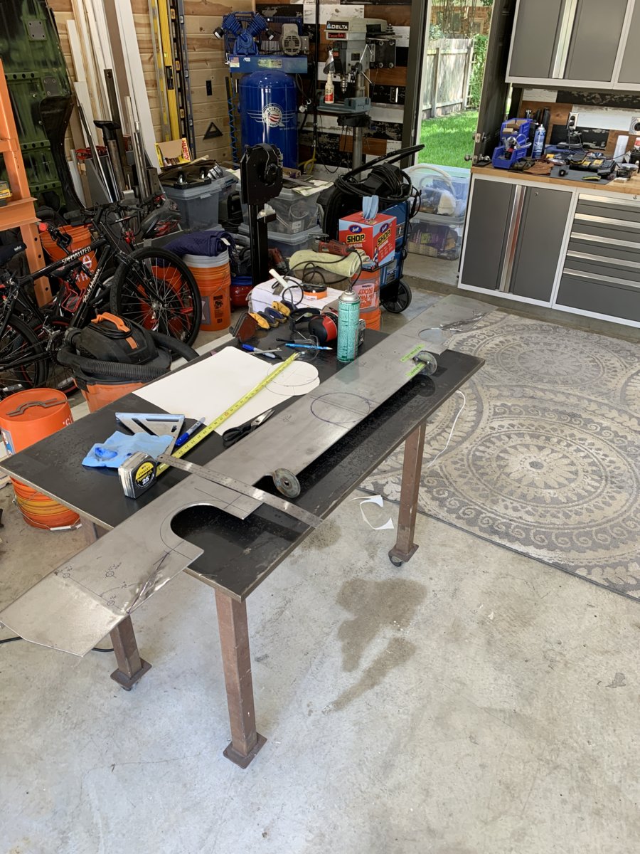
The first obvious issue was that there was no hole for the driveshaft to pass through the "step-up" panel area. After the final installation of the dual exhaust, it seemed like a good idea to open up the areas around those 3" tubes as well.... there's no real value in keeping everything super tight, as it's only going to trap heat anyway. After careful measurements, the hole center was determined and the trusty HyperTherm was powered up (for the first time in YEARS!) to make quick work of things.

(There are a couple of Blue Sharpies in this photo... for those of you who like that kind of thing...) :)
full


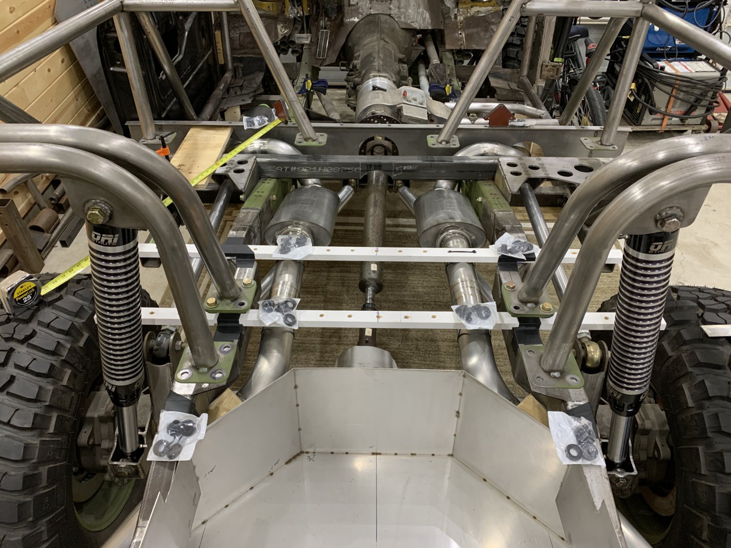
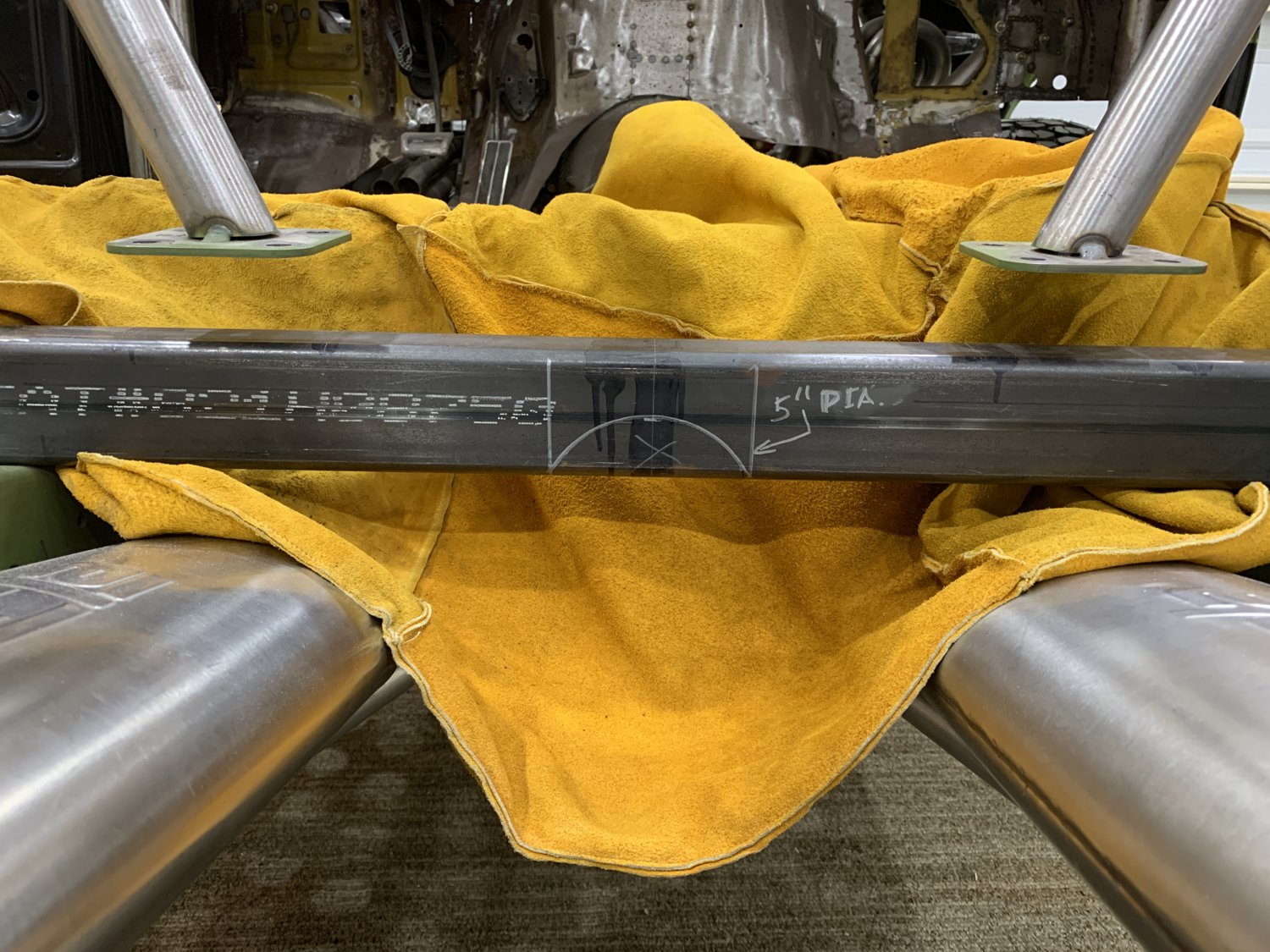
After several mock ups, the driveshaft was in place through the new passthrough hole, but the crossmember did not allow the other end of the driveshaft to swing all the way up into position. (This is the kind of thing you'd NEVER notice at normal ride height and would be a disaster on the first big landing!). This one was a bit trickier with the plasma cutter since the new exhaust was so close to the cutting area, so the heavy welding blanket was used to protect those nice finishes during the cutting process.

full


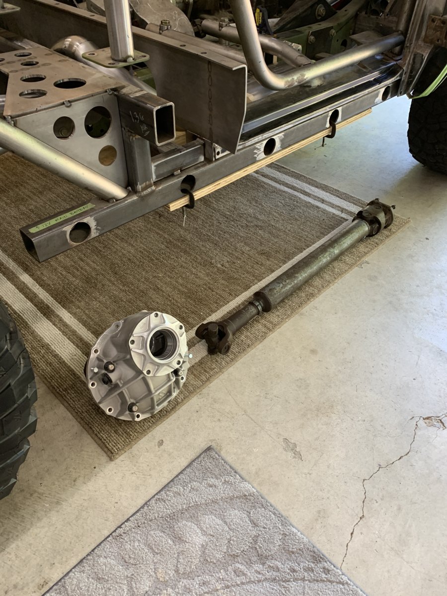
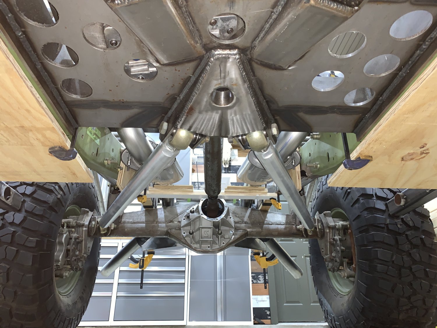
By midnight, and after at least a dozen installations.... the driveshaft was in place! (see photo below) Astute viewers will notice that the pinion support was removed to allow the driveshaft to fit. It's clear that the old driveline setup (396/TH350/NP205... and factory setback) put the output substantially further forward because the old driveshaft is WAY too long for this application now! :haha: This is a High-Angle Driveline CV shaft with integral parking brakes setup. It was pretty expensive (even back in 2003) and probably has less than 4000 total miles on it. So it's definitely going to get cleaned up, shortened and reused. Probably the simplest way will be to carefully cut the weld at the top of the tube just before it goes into the CV. A lathe would make that easy... but if the two parts can be separated with a cutoff wheel, maybe there is a local shop that can clean up the CV to give it a new factory surface to reassemble into a shortened main tube? :thinking: It would obviously need to be re-balanced but it seems like almost any decent driveline shop should be able to handle that part. Seems silly to ship this all the way to CA just to have Jesse take care of it.

@blazinzuk (Photo just for you. 100% Homer Bucket Free)

full


So the driveshaft is in, but now that it is... the idea of running a long, narrow 2 Gallon air tank between the mufflers is CLEARLY not going to work. There just isn't any clearance above the driveshaft at full-compression. Everything looks a lot easier when you build at "ride height". :dunno:
Moving the air tank (and probably using two small 1 gallon units) will probably put them in the rearmost corners on either side of the fuel tank... which was supposed to be the location for the Viair compressors... it's a real game of musical chairs right now, but ultimately it will get sorted out.


#FORWARD


-G


No space for an air tank on top of your monster crossmember thing on the drivers side? (Right above where all those 2”-ish holes are cut out?
 
No space for an air tank on top of your monster crossmember thing on the drivers side? (Right above where all those 2”-ish holes are cut out?

Negative GhostRider..... There is some internal bracing in there, and it's only as tall as the framerails. :dunno:


-G
 
How much pressure in the air tank?
Can you custom mold it to fit around obstacles?
 
Greg, at this point I know you have to have pondered using the cage or some of the chassis bars as an air tank itself? You have to make sure every end is sealed up and maybe put a fitting under one of the bed mount ends or something, but it could be done. I've seen drag racers use them as vacuum canisters on street cars before. If you have 1.75" x 1/8" wall round tube about every 11 ft is a gallon inside of it. But you also have to plan ahead and drill a hole inside every joint for the air to pass through before you weld it up so it's all interconnected internally. And the welds have to be air tight. Obviuously you can't do this with large box frames as it may be too much pressure but roll cage tubing can take it easily as its a small round section with means low stress on the metal. A big 3 x 6 piece of rectangular could bow out on the sides pretty easy and I wouldn't recommend it. Stick with the round tubing.
 
Or maybe a cylindrical tank mounted inside the spare tire wheel offset? Was gonna suggest the spare tire itself, but guessing you need more than 20psi. :D
 
How much pressure in the air tank?
Can you custom mold it to fit around obstacles?

200PSI... Decided to buy the Viair 480C (2 pack) so that there would something to start mocking-up with. They are a lot smaller than expected, which may allow them to go somewhere unexpected and save the larger spots for air tanks.

Greg, at this point I know you have to have pondered using the cage or some of the chassis bars as an air tank itself? You have to make sure every end is sealed up and maybe put a fitting under one of the bed mount ends or something, but it could be done. I've seen drag racers use them as vacuum canisters on street cars before. If you have 1.75" x 1/8" wall round tube about every 11 ft is a gallon inside of it. But you also have to plan ahead and drill a hole inside every joint for the air to pass through before you weld it up so it's all interconnected internally. And the welds have to be air tight. Obviuously you can't do this with large box frames as it may be too much pressure but roll cage tubing can take it easily as its a small round section with means low stress on the metal. A big 3 x 6 piece of rectangular could bow out on the sides pretty easy and I wouldn't recommend it. Stick with the round tubing.

Yeah, we've joked about that for years now.... not sure it's worth the trouble or not, though 11 feet isn't really hard to find in a rollcage. The two main bars that run from the A-pillar to the C-pillar are more than that by themselves.... so I'd only have to ensure that the two ends were perfectly sealed to get a "tank" out of it. Hmmm..... :thinking:


-G
 
Don't pressure up your cage... Bad idea. In the event of an actual roll over you will all ready have a lot of stress/ tension built up in your steel. A bend at the wrong place and it ruptures could mean not only your cage failing easier, or chunks flying.
 
Think putting air pressure into cage tubing would be a bad idea, esp at 200psi. There's a lot of surface area, and gonna a lot of stress on that tubing, esp next to you and your family. I'm not an engineer but don't believe I've ever seen DOM rated for any pressure, and welding the ends would kind of nullify that anyhow. Perhaps several smaller bottles, such as the powertanks or even scuba tanks may be easier to fit into the corners. And rated for psi.
 
Actually they used to pressurize tubing in some super lightweight structures to make it less likely to buckle and collapse when using thinner wall tubing to save weight, I don't recommend that. Also, I'm not recommending it with square or rectangular tubing as it can cause walls to bend etc. But with small round tubing of significant wall thickness, 120 psi is fine. Obviously you would still have a pressure relief valve in a safe place for the pressure to release in the event of an overpressure. Compressible fluids/gases can be much more dangerous than incompressible, so you want to vent it in a place that isn't near someone's ears or anything fragile. But the stresses from a rollover or even thermal stresses will likely be way more than the 120 psi in a small tube.

The most critical thing be to place a drain in the lowest spots, so you can be sure to let any moisture out, as internal corrosion over time could cause a weak spot and the ends of the tube and welded joints will already be the weakest point.
 
Last edited:
2020.04.29 - UPDATE! - NEW PARTS...


The challenge with the current part of the build is laying out all of the necessary items underneath the truck and making sure that they fit properly even when the bedfloor assembly is reinstalled.

Putting the bedfloor in place gives 100% certainty about the available room remaining, but makes everything about 1000x more difficult to work on since it's all got to be done underneath and upside down.

To hang the mufflers, it seemed that the "speedhole" areas in the original bedfloor would make for great anchor points for bushings and brackets. If only there were some way to identify where those would land relative to the frame, and WITHOUT reinstalling the entire bedfloor again.... :thinking:

Ultimately, the idea was this:

full


Make 49" strips of wood and transfer all of the hole positions to them. Then carefully drop them in place at the correct intervals on the frame. The idea is to weld-in a threaded washer in the holes that are closest (and most useful) for hangers...then a small segment of threaded rod creates a drop-hanger for the bushing to attach.

You can see how those holes work in this photo...

full


For now, the mufflers are just cinched-up with zipties but the plan looks like a workable one.

full


NEW PARTS!

The Viair 480C (Dual compressor 200psi) showed up yesterday.

full


They are nice and small but weigh about 12 Lbs each! They are beefy little units and may not be as hard to find a mounting spot as originally feared.
Here's a reference shot (inside the fuel tank) just to give a sense of scale.

full


The search continues for a decent air tank (or two). It seems like a cylinder shape that is between 16" - 18" long and about 6" diameter would fit (barely) on either side of the fuel tank and would not hang down below the rest of the bodywork... that's roughly 2 gallons each. So by going slightly smaller per side, it should be easy to get a total of 2 gallons of air into those rear corners.

That puzzle is next.


-G
 
What are you doing for a heater ? What about all that space above the passenger's feet for tank locations.


You talking under the dash?

VintageAir is probably going to eat up most of that.

16" x 6" tanks seem doable out back somewhere.... don't give up hope. :)


-G
 
Why do they have to be out back?
What about inside the bumper skins? Front or rear?
 
Top Bottom