2020.06.04 - UPDATE!! - MUFFLER BEARINGS....
No bearings were hurt in the making of this update.
It's been a while folks, sorry about that... lots of hours at my paying job. Not so many available to spend in the garage... but progress is still being made.
When last we spoke
@folkenheath was teasing me about being stubborn about my strategies to tie the muffler hangers to the bedfloor supports. While I'm sure it could have been accomplished, the idea of building a complete rolling chassis (complete with mufflers and hangers installed) won me over, and being able to test fit everything without reinstalling the bedfloor was too attractive to ignore
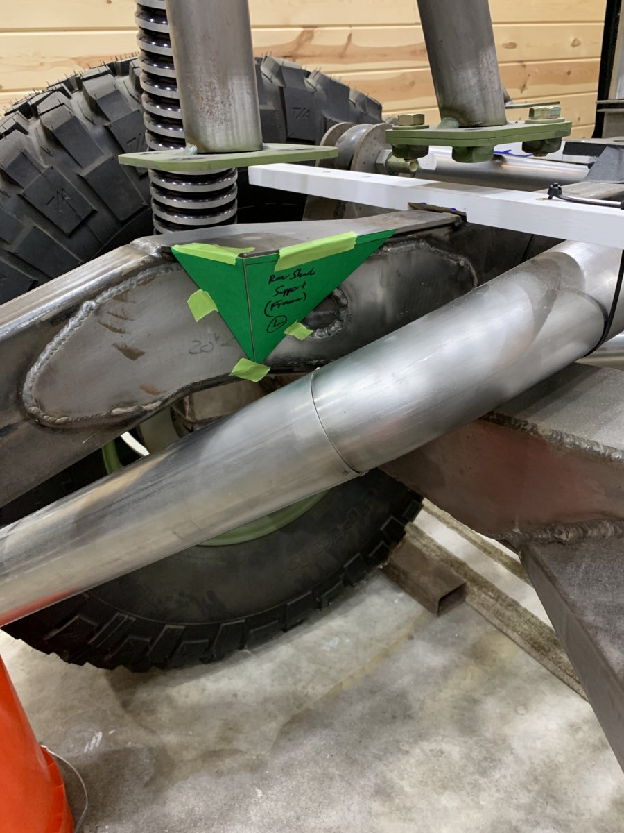
Step 1: Install a small triangulated support under the floating tube that holds the rear ORIs in place. This has been an "IOU" project from when the rear back-half frame was built. There just wasn't a well supported landing pad for that tube but the fix was simple enough to make.
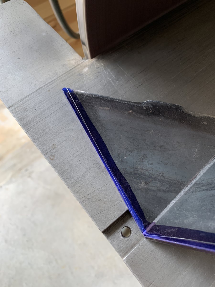
Paper templates to the rescue:
Never did find my last bottle of Dykem marking fluid from the TX move, so Amazon sent me a new one... it felt good to get back to marking and scribing metal like the old days and dressing-down the edges in a hurry on the 20" APEX grinder.
The test Fit....... fits! A couple of tack welds for now is enough. There is a TON of finish welding all over this frame and rollcage to do someday, but don't want to commit to fully welding joints until there is 100% certainty that they won't need to be cut or relocated by some future build step. Tacks cut easier than full perimeter welds.
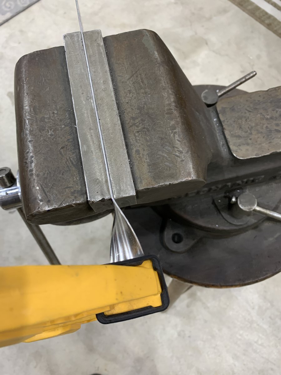
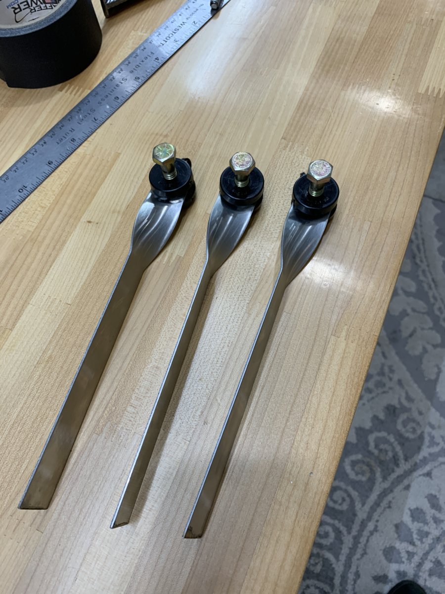
A number of different concepts were sketched out, but the simplest and most elegant seemed to be using 1" wide straps of T304 as hangers, installing the poly bushing on one end and then shaping them to fit the circumference of the 3" exhaust and welding them on.
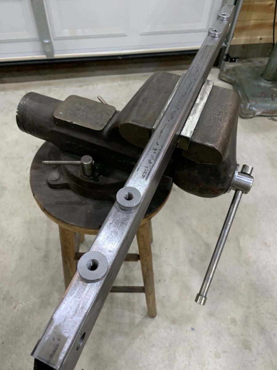
The straps were clamped in the vise, then a second bar clamp was used to rotate the end by 90* so that the mounting bolts would be in alignment with the new 1"x2" crossmember
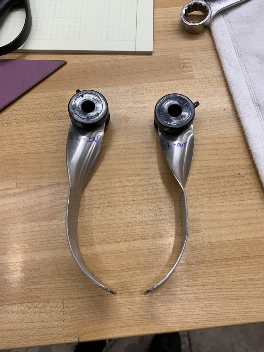
After installing and bending and marking the straps were cut down to the final lengths and were ready for welding and installation on the exhaust tube
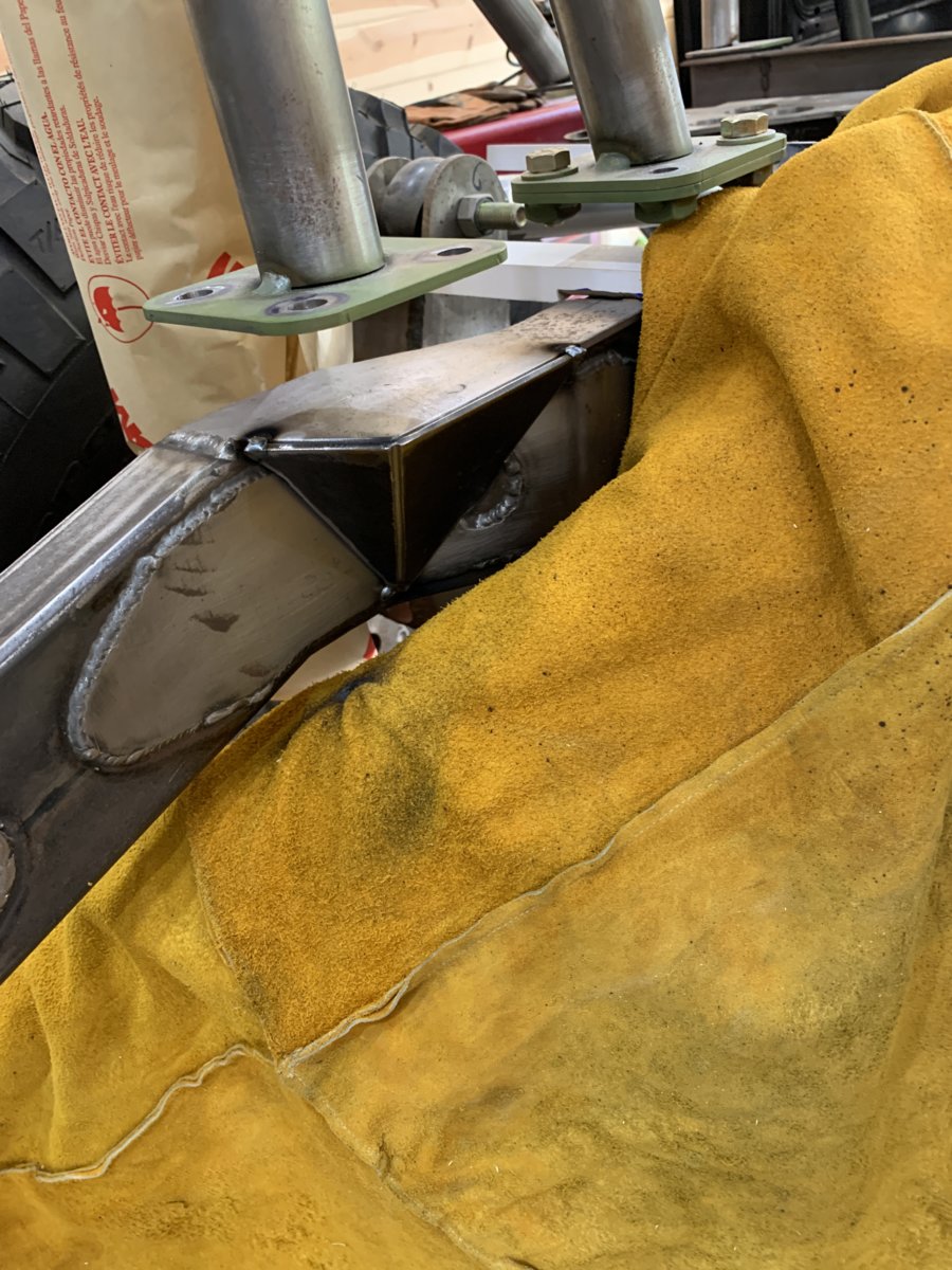
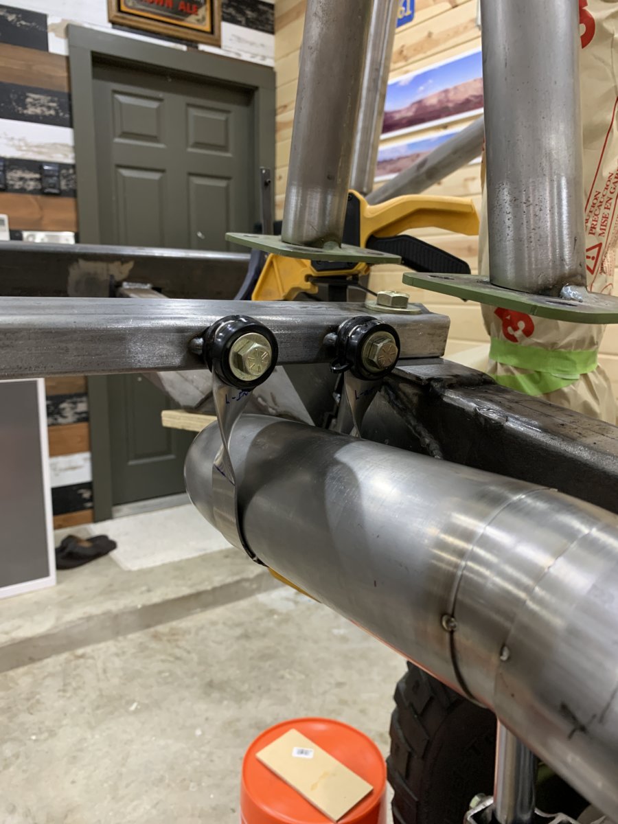
Here's a shot of the crossmember. Nothing too fancy, just a low-profile .125" wall tube with threaded inserts to hold the bushings. A couple of threaded inserts were welded into the top of the frame as well so that this crossmember could just drop down easily and snug into place without a long through-bolt or extra brackets. Did weld in some internal supports so that the tubing wouldn't crush when the bolts were torqued-down. Thinking back now, for such a simple-looking crossmember there were actually quite a number of process steps involved to get it built and installed as intended.
So here you can see the end result of the effort. The exhaust is supported on both sides with a bushing to prevent excessive lateral movement and to keep the weight of the long bent section of tube from twisting out-of-position and causing the exhaust tips to sag lower than desired.
So that's the update.... lather, rinse, repeat for the remaining exhaust locations... but now that it's been done once and looks good, it's just a matter of logging hours and replicating parts.
-G


")
")