That thing is cavernous! Those benches are like couches too. Sweet road trip mobile!
CK5

You are using an out of date browser. It may not display this or other websites correctly.
You should upgrade or use an alternative browser.
You should upgrade or use an alternative browser.
89 Suburban - The Canyonero: Rear Suspension Time!
- Thread starter nutt7
- Start date
Budget friendly build for General off-roading with an emphasis on camping and self reliability featuring a host of self-built, DIY mods.
I think that's the same master cyl I'm running and I love how my brakes feel and work. What's the reason for the line adapters? Mine bolted up just fine, Did you swap them front to back or something? Do you front brakes lockup before the rears in a panic stop? I was going to install a manual adjustable prop valve to turn down my rear brakes but I may just swap the lines if possible cuz that would be lots easier.After a freeway trip and some more in town driving, all is working well still. Rolls straight and quiet. I just retorqued the u-bolts today. They relaxed and everything settled in and they were about 20 ft lbs loose. Now I need to get these tires off road! I hope the rain allows a trip next weekend. Anyway, here are a couple of pics of things I don't think I mentioned yet.
Top left is the final shot of the angled spring perch and counter-angled ez-inch. Bottom left is the conversion u-joint needed for this axle swap. Luckily, (I guess), a transmission shop ruined my stock driveshaft so they had one made with 1350 flanges. The aam has a 1410 yoke. This u-joint by neapco (pn: 2-1435) marries those two. You might notice the u-bolts I thought I could use. The threads in the yoke were so caked I thought it was straight all the way through. Maybe one day I'll mod it to work. Until then, the old strap n bolts went in. The right is the brake line T I used. I bent the bracket so it pointed the T in the right direction. It is actually the aam line. It is longer than the one that came with my lift. That pic is with the axle fully drooped. You can also see the lines I made to get the T to the passenger side and one of the flares on the aam was cracked anyway. Also, the vent tube is much smaller on the aam. I went ghetto fab and cut a short piece of the aam hose and jammed it up the old breather hose, lol. It's super tight!
Here is the hydroboost, master cylinder, and brake pedal rod. Don't mind the wires and zip ties, I'm still cleaning up. You can also see how I tapped the return line. It's tapped after the cooler, and the perpendicular hose is from the booster. This was the recommended way. Hydroboost pedals have a larger stud for the rod eye. Little did I know, within hydroboost studs, the 94 hydroboost eye was too loose for the 70s pedal. Luckily I hung onto the 70s eye. I threaded it and lock tited the coupler nut to it. I had to thread it so I could change the seals on the pedal piston without removing the rod from the pedal piston thing (which is a pain). I can also now service the unit without removing the whole thing from the firewall, and have slight brake pedal height adjustment.
Next up: clean up wires, wheel spacers, some corrosion control, refinishing the wheels, fix upper shock mounts, and parking brake solution.


I think that's the same master cyl I'm running and I love how my brakes feel and work. What's the reason for the line adapters? Mine bolted up just fine, Did you swap them front to back or something? Do you front brakes lockup before the rears in a panic stop? I was going to install a manual adjustable prop valve to turn down my rear brakes but I may just swap the lines if possible cuz that would be lots easier.
I ran the lines that way to match front brakes to the chamber closest to the firewall, which is how it's supposed to be, I think. It feels good, but I also think the rears get a little more pressure. On pavement the tires start dragging when the weight shifts forward. Being a suburban though, I have more weight on the back so I think I'll leave it.
Went camping. It was great! Truck did well too. I did over 20 miles of pot holed forest road and things seem ok still. Braking was confident on the quick stops when the freeways were backed up. A few pics:
Loaded without passengers:

With passengers. Notice how comfy they are:

Our spot. Notice my leveling blocks? The toolbox is on a harbor freight hitch carrier with HF led lights. I used old radiator mounts to mount the lights, lol. We load our bedding and other lightweight stuff in it for the drive. Then we swap it with our food items for camp. I like it because it's weatherproof and it locks, and frees up luxury dog space and still allows me to not have to stack my gear too high for visibility.

The rest is all pics of the fam and the area we camped, near Bare Mountain, east of Seattle.


Emma the Kelpie, Dutch the mastiff, and Danielle the wife. Oh and Snickers the shih tzu on the blue chair!
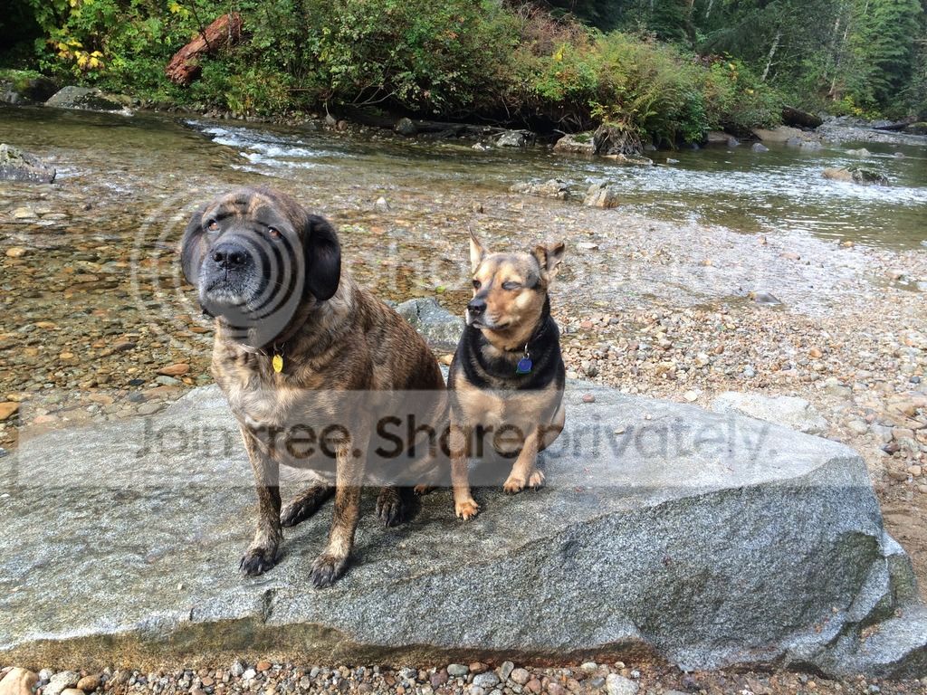
Dutchess:

Emma napping:


And me, smoking a pipe and drinking whiskey while sitting in the creek!

Nice! 
That's some pretty country up there!
I went to the jy recently and came across a 99 escalade. I stole the gentex 177 rear view mirror with autodimming, compass, auto headlight output, and temperature. As well as the temp sensor, and whatever wiring I could get. $19 isn't too bad. I usually only see the compass ones left behind.
It fit nicely on the factory mount. I mounted the sensor on the core support, between the parking light and the radiator opening. The rest was just running wires and a little soldering. I used some left over trailer brake wires. Works great!


I bought some park brake stuff so I can get that hooked up too. I also snagged some low speed resistors for my windstar fans to make a soft start circuit or be able to run them on low speed. These will be done soon I hope...work has me studying for a promo board
I've been planning a rear bumper. The main reason is for a rear tire carrier since I have a full size spare now. I'm posting today to share my idea and get some input. I want the base to be a 2x6x1/4 rectangle tube as the main piece, with 1" thick recovery points that pass through to mount to the frame, with some other minor details that aren't yet important. My spare will be mounted on the driver's side to allow visibility on the passenger side. I'm entertaining the idea of a fold down carrier and here's where I want to bounce ideas off of you.
I was thinking of getting four of these bushing/dom tubes and some weld on tabs:

I would weld two pairs of tabs as far down as possible on the lower face of the 2x6, maybe 12-15" apart, and the other two pairs near the top of the bumper face so they are a few inches over the lower ones. The tire support frame will be round tube, with the bushed doms welded in so the tire support swings down on the lower bushed doms and the upper bushings will have pins that are removed to allow it to swing down. The tire support frame will also go outside of the tire (like most swing downs) to allow the tire to rest nearer the body. My loose estimations will have the tire resting on the ground at a 30 degree angle or so.
Know what I'm getting at or will a sketch help?
I have more details worked out, and reasons for the design, but my hope was to get opinions on any shortcomings of my proposed idea about the swing down portion. It seems like it'll be plenty strong to support the tire and frame in this configuration, but I also see that the pivot point and security point are very close together which puts more stress on the mounts. The leverage combined with the bushings might cause too much movement too. What say you?
I was thinking of getting four of these bushing/dom tubes and some weld on tabs:
I would weld two pairs of tabs as far down as possible on the lower face of the 2x6, maybe 12-15" apart, and the other two pairs near the top of the bumper face so they are a few inches over the lower ones. The tire support frame will be round tube, with the bushed doms welded in so the tire support swings down on the lower bushed doms and the upper bushings will have pins that are removed to allow it to swing down. The tire support frame will also go outside of the tire (like most swing downs) to allow the tire to rest nearer the body. My loose estimations will have the tire resting on the ground at a 30 degree angle or so.
Know what I'm getting at or will a sketch help?
I have more details worked out, and reasons for the design, but my hope was to get opinions on any shortcomings of my proposed idea about the swing down portion. It seems like it'll be plenty strong to support the tire and frame in this configuration, but I also see that the pivot point and security point are very close together which puts more stress on the mounts. The leverage combined with the bushings might cause too much movement too. What say you?
I've been planning a rear bumper. The main reason is for a rear tire carrier since I have a full size spare now. I'm posting today to share my idea and get some input. I want the base to be a 2x6x1/4 rectangle tube as the main piece, with 1" thick recovery points that pass through to mount to the frame, with some other minor details that aren't yet important. My spare will be mounted on the driver's side to allow visibility on the passenger side. I'm entertaining the idea of a fold down carrier and here's where I want to bounce ideas off of you.
I was thinking of getting four of these bushing/dom tubes and some weld on tabs:
I would weld two pairs of tabs as far down as possible on the lower face of the 2x6, maybe 12-15" apart, and the other two pairs near the top of the bumper face so they are a few inches over the lower ones. The tire support frame will be round tube, with the bushed doms welded in so the tire support swings down on the lower bushed doms and the upper bushings will have pins that are removed to allow it to swing down. The tire support frame will also go outside of the tire (like most swing downs) to allow the tire to rest nearer the body. My loose estimations will have the tire resting on the ground at a 30 degree angle or so.
Know what I'm getting at or will a sketch help?
I have more details worked out, and reasons for the design, but my hope was to get opinions on any shortcomings of my proposed idea about the swing down portion. It seems like it'll be plenty strong to support the tire and frame in this configuration, but I also see that the pivot point and security point are very close together which puts more stress on the mounts. The leverage combined with the bushings might cause too much movement too. What say you?
Sounds pretty close to the DIY4X kit.

Kert's design certainly planted the seed of a swing down option! However, I want mine to be off to the side (I want barn doors in the future, and I want to be able to open the passenger side without moving a tire), and my mounts/pivots will be external. I have an idea for an assist, but it's not like the DIY4x at all.
Kert's design certainly planted the seed of a swing down option! However, I want mine to be off to the side (I want barn doors in the future, and I want to be able to open the passenger side without moving a tire), and my mounts/pivots will be external. I have an idea for an assist, but it's not like the DIY4x at all.
Hope you got a big bag of popcorn. Wife, dogs, and I are livin on a lower enlisted gubment income...but I do have a few things to sell 
Hope you got a big bag of popcorn. Wife, dogs, and I are livin on a lower enlisted gubment income...but I do have a few things to sell
I understand. My builds have been on ice for a couple years now, and finances are a piece of that. And that's why I read stuff on here instead of getting out and actually doing it.

Here are some sketches. They are to scale, estimating a 36x13 tire. Each box is 3". Questions? Thoughts?

Stowed and open. The tire will stand vertically if I net 13" more lift, lol!


Stowed and open. The tire will stand vertically if I net 13" more lift, lol!

Better idea then trying to pick the dang thing up
Like to see the lift assist you do.
Mine's kinda like that, except centered, and holds a bloody heavy Toyo 37". I ended up putting horizontal reinforcements at the body crease (i.e. right above the tail lights). Coupla pix:


Each wing holds a jerry can, but also latches onto the center tire holder. They then swing out to let the tailgate drop.
Note that with that 37x13.50, the center section is just slightly over what one guy can comfortably lift off the ground. I end up either using a helper (easy with two guys) or winching it when solo (as seen in the first pic.) YMMV depending on your tire, back strength, and that angle at the bottom. Do put the bottom hinge point as low as you can go to keep that angle minimized (ie closer to horizontal.)
Other thoughts: do a mockup first with cardboard, but I suspect you'll find you can block a lot more of your rearview than you think. Also, if you're going to attach to the body, do it as high up as you can (gets more leverage), and sandwich the metal for strength. Umm, see


That's flat stock, bent with a sledge to match to body curve. Thick one on the inside, drill and tapped, then thinner one outside with holes through, then finally chunks booger welded around the circumference for further reinforcement.
And if you think of any clever lift assist/spring arrangement, do a good writeup so I can steal it
-- A
Each wing holds a jerry can, but also latches onto the center tire holder. They then swing out to let the tailgate drop.
Note that with that 37x13.50, the center section is just slightly over what one guy can comfortably lift off the ground. I end up either using a helper (easy with two guys) or winching it when solo (as seen in the first pic.) YMMV depending on your tire, back strength, and that angle at the bottom. Do put the bottom hinge point as low as you can go to keep that angle minimized (ie closer to horizontal.)
Other thoughts: do a mockup first with cardboard, but I suspect you'll find you can block a lot more of your rearview than you think. Also, if you're going to attach to the body, do it as high up as you can (gets more leverage), and sandwich the metal for strength. Umm, see
That's flat stock, bent with a sledge to match to body curve. Thick one on the inside, drill and tapped, then thinner one outside with holes through, then finally chunks booger welded around the circumference for further reinforcement.
And if you think of any clever lift assist/spring arrangement, do a good writeup so I can steal it
-- A
Last edited:
Mine's kinda like that, except centered, and holds a bloody heavy Toyo 37". I ended up putting horizontal reinforcements at the body crease (i.e. right above the tail lights). Coupla pix:
Each wing holds a jerry can, but also latches onto the center tire holder. They then swing out to let the tailgate drop.
Note that with that 37x13.50, the center section is just slightly over what one guy can comfortably lift off the ground. I end up either using a helper (easy with two guys) or winching it when solo (as seen in the first pic.) YMMV depending on your tire, back strength, and that angle at the bottom. Do put the bottom hinge point as low as you can go to keep that angle minimized (ie closer to horizontal.)
Other thoughts: do a mockup first with cardboard, but I suspect you'll find you can block a lot more of your rearview than you think. Also, if you're going to attach to the body, do it as high up as you can (gets more leverage), and sandwich the metal for strength. Umm, see
That's flat stock, bent with a sledge to match to body curve. Thick one on the inside, drill and tapped, then thinner one outside with holes through, then finally chunks booger welded around the circumference for further reinforcement.
And if you think of any clever lift assist/spring arrangement, do a good writeup so I can steal it
-- A
That's cool! How thick are the mounting tabs on the bumper? My only major concern is having all four mounting points close together. I've been brushing up on a little physics for this thing and I've already changed the pivot location. They will be higher up (opposite of your suggestion), so the weight is nearer the fulcrum and it will come closer to standing when folded down, making it easier to dismount and be under the tailgate. The heaviest lifting will be when the tire is parallel to the ground. I'm in good shape now, but for how long
 ?! At 36, sometimes I wake up and move something wrong and I'm like
  ...and that's why I want that assist.
Like to see the lift assist you do.
I need a little more calculating and planning before the idea is worthy of a post...it's quite simple though, nothing fancy.
I think the tabs are just 1/4", probably Kert's. Two of them on each bushing separate by a coupla feet is fine for side-to-side. I do wanna redo the wings in heavier tube as there's too much wobble there, but the center section is good.
-- A
-- A
Didn't notice it but do you have part numbers or sizes on the adapters you used? I have the same master with my lines hooked up like normal and my rear locks up first and wants to pass the front in the snow . I was gonna try to swap the lines on the master and see what happens before I go splicing in an adjustable prop valve.I went back to AZ to return the fitting. We ended up swapping it out take a look at the pic:
The one on the left is the original. Notice the threads and the size of the flare seat. Hopefully this one will seal.

Latest Posts
-
 '99 4 Door Tahoe SAS Build, Taking it back a few years
- Latest: Babaganoosh
-
-

-

-


