Just to throw a random idea out there, have you considered stacking your 3 switches on a multi-level bracket, with the dials all facing outboard?
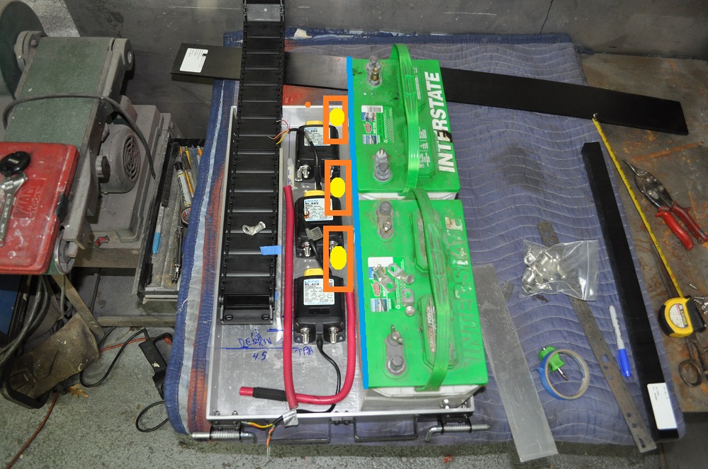
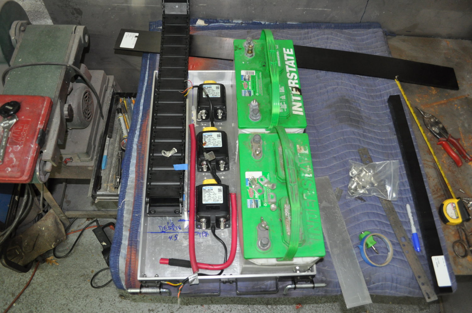
Using your picture as a guide:
The cable bundle would need to arc 180° out of your track down and to the right, then the bundle would transition from being flat: _ to being vertical: | as it completes the 180° and transits to the back of the tray, running in-between the battery and the switches.
With the switches stacked and offset perhaps 2-3 inches back from the tray exit, you would have twice the distance between the switches and the batteries (to be consumed with cable and assorted brackets and hardware to ensure nothing moves)
Additionally, all the actual connections would be facing the back of the tray, and not normally visible (making for a cleaner appearance)
I could see such an arrangement making the appearance of the cables on top of the batteries a bit cleaner too.
No idea if you have enough vertical clearance though.
If you're interested though, I could probably throw together some mockup files in CAD to better explain my idea.
I might do it anyways.. keep me entertained tonight


")

 and yeah, feel free, even a crude MS paint drawing would be killa...