2021.01.18 - !! UPDATE !! - CHRISTMAS FINALLY CAME....!!!!
It took more than a month, but the Christmas present for the MAW build finally arrived today from Mittler Brothers.
The English Wheel was a great addition to the shop and the capabilities for working sheetmetal, but the piece that I'd really been looking forward to finally arrived today.
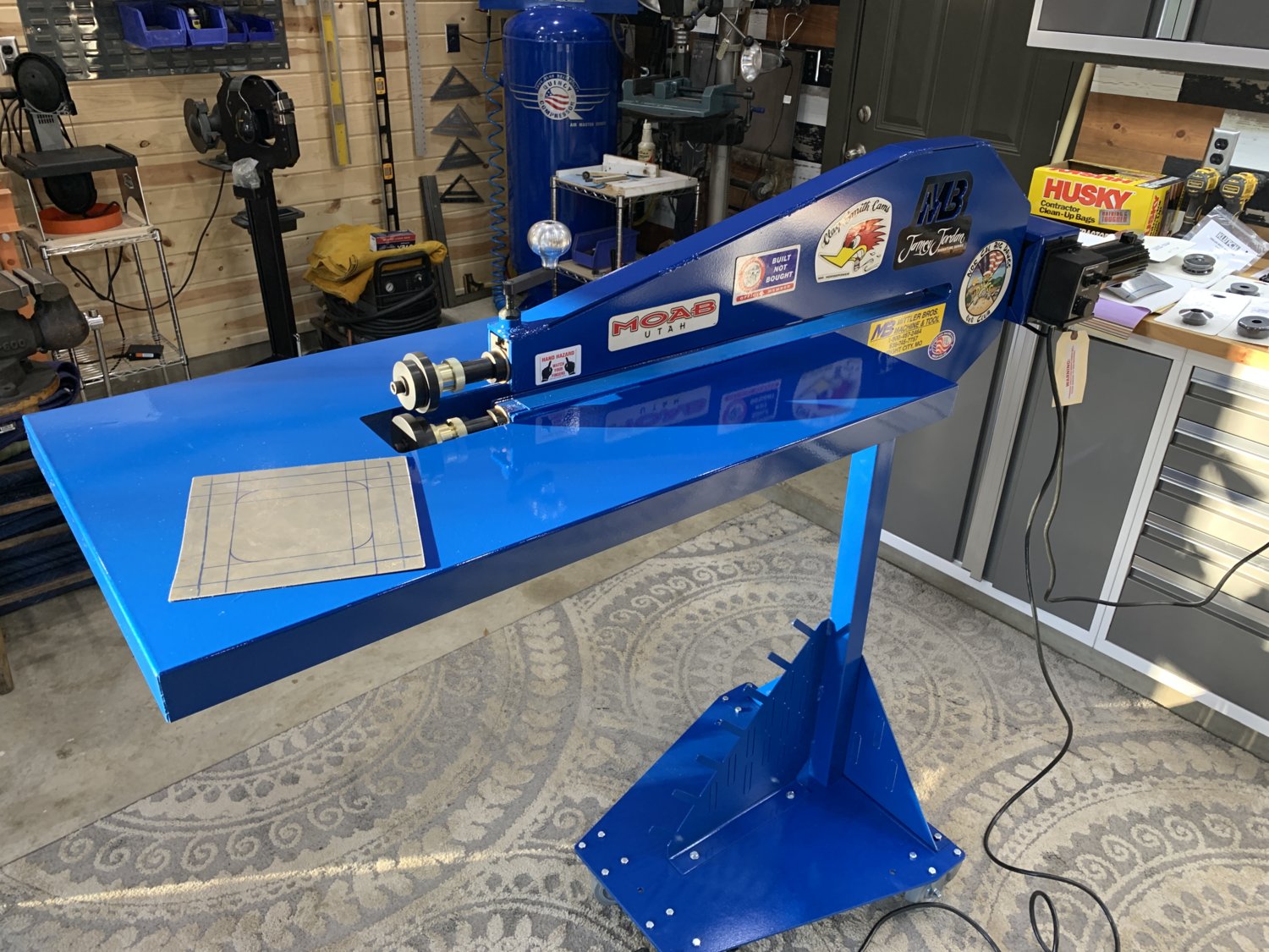
It's a bit larger than expected, but with the table folded down, it should tuck-away into a corner reasonably well. But for now, let's just keep it out in the middle of the floor and have a little playtime!!
As usual, instead of using a thin-gauge steel to get familiar with it... we went straight for it's maximum (16 GA, .060") since that what was handy. It's also the hardest to work with but ultimately the machine still handled it fine.
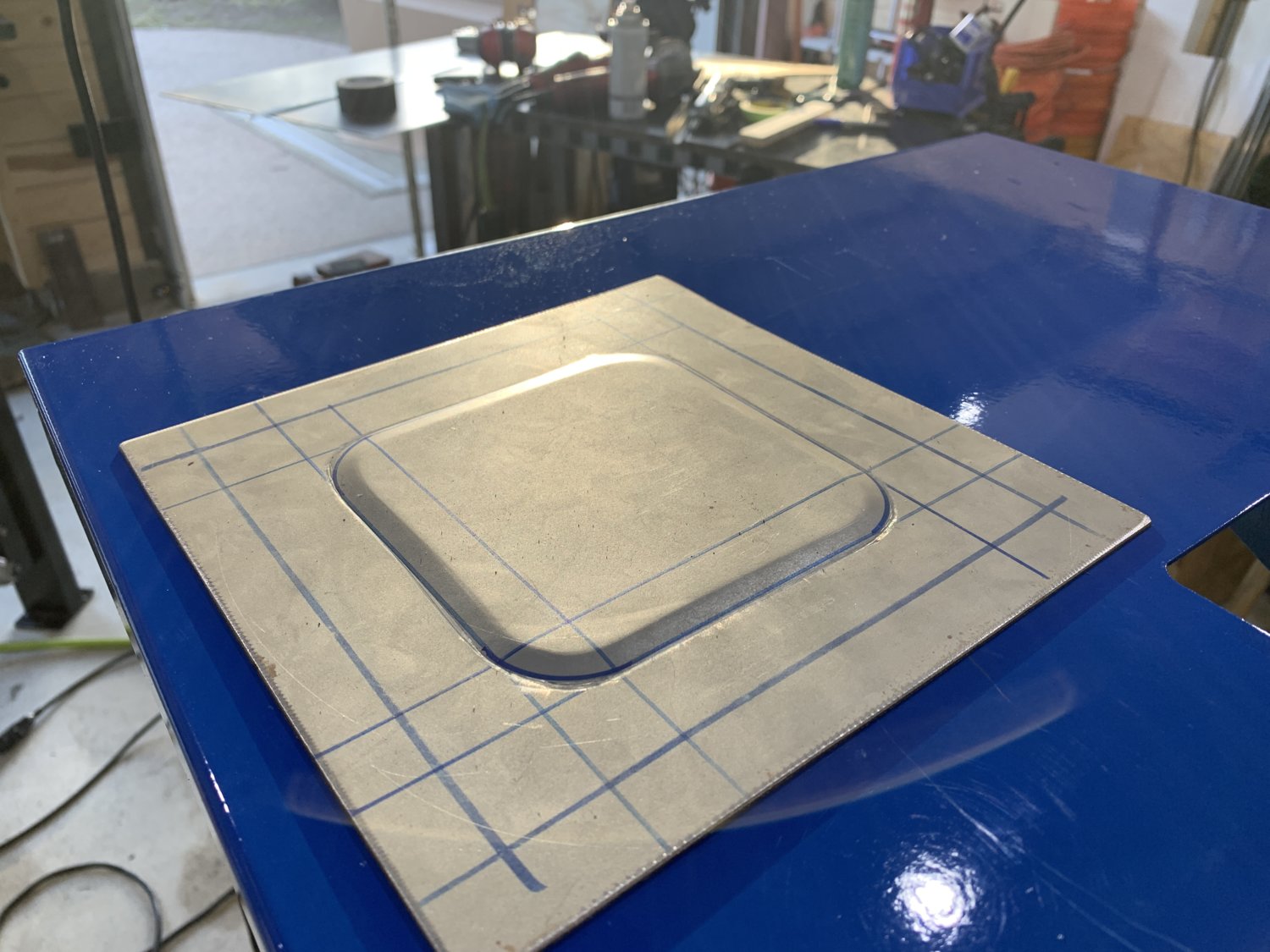
First impressions of beadrolling..... It's harder than it looks, you need REALLY good lighting near the dies to see exactly where the touchpoint is so that you can make your turns accurately, and swinging the metal around a sharp radius turn is going to take a lot more practice (and a slower pedal speed in those corners). Totally fun machine though and I can't wait to experiment with each of the die sets to get more familiar with all of them.
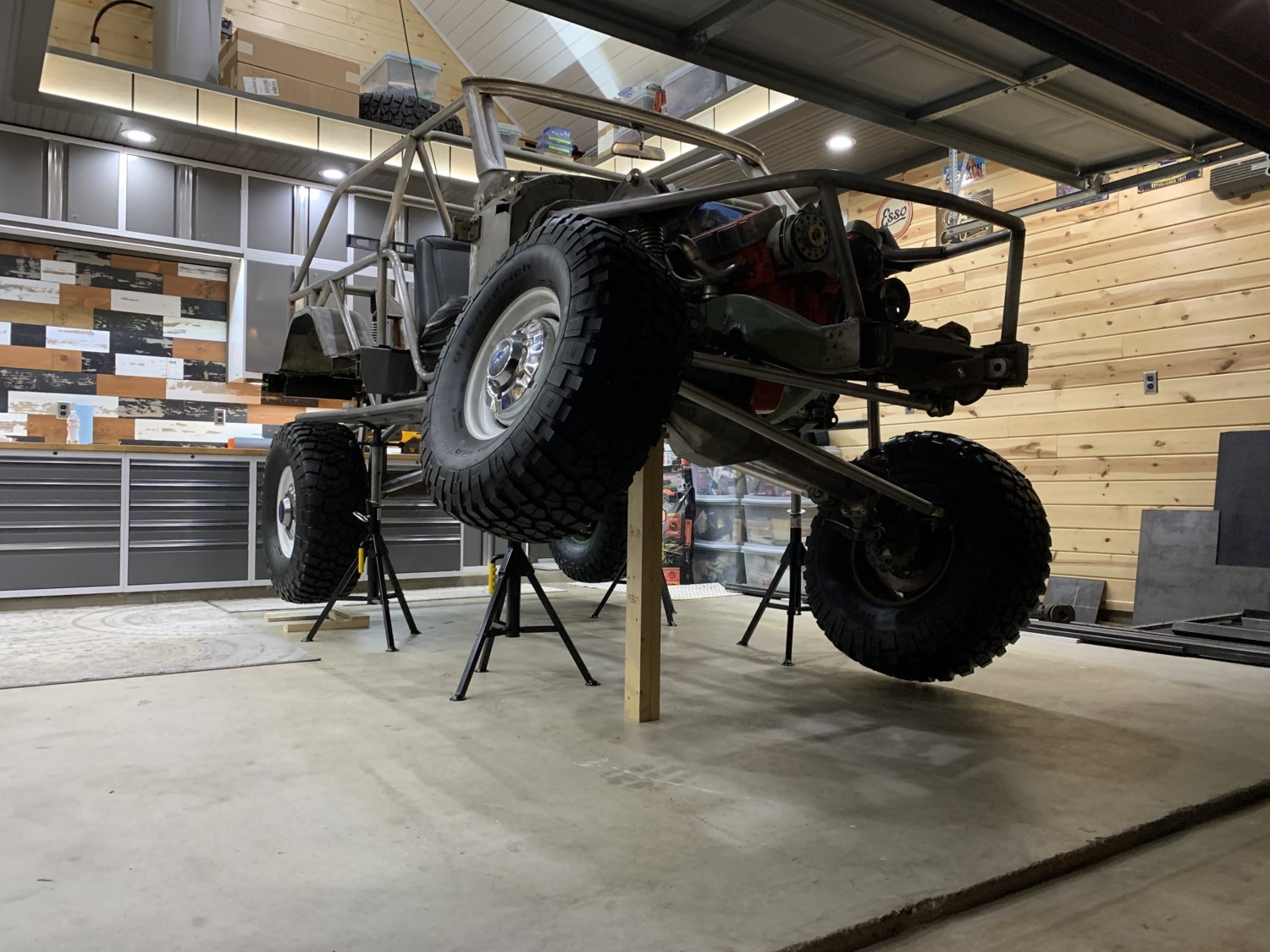
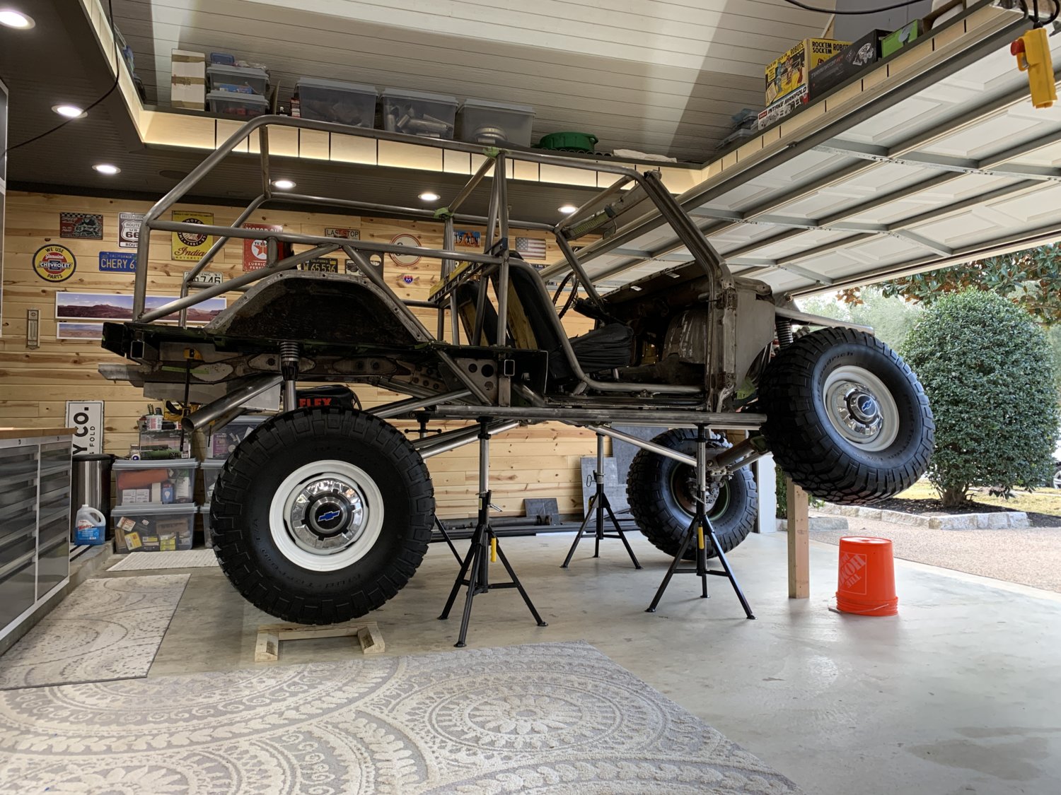
The other big initiative was to use the new 49" tall jackstands to finally get the truck ALL the way up in the air and cycle the front suspension in ways that were not possible in the NH garage due to the low ceiling rafters. The main objective was to confirm that there were no interferences at full bump / full droop with the wheels & tires installed AND also check the full- lock steering at the same time. After a lot of effort and adjustments of the jackstands, the photo that had never been possible before was finally captured late Sunday night.... You can see that there is just a small amount of daylight under the drooping driver's side tire and that ORI strut is 100% maxed-out for travel.
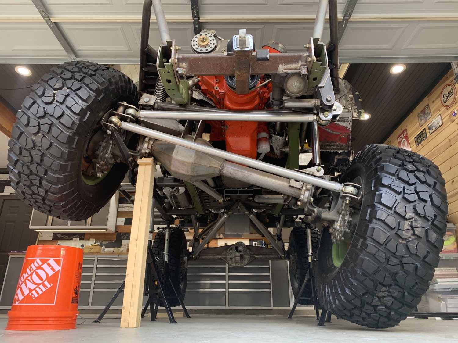
That was a pretty exciting victory and set everything up nicely for this morning. With better lighting, it was compulsory to get a least a few more beauty shots before starting the "full-lock steering" tests... The nitrogen had to be released from the passenger side strut to allow this articulation....otherwise it just kept wanting to lift up off the jackstands. (NOTE: The 2x4 in this photo is only supporting the weight of the axle housing and the wheel/tire.)
Of course, it wouldn't be a proper build day in the MAW shop without some kind of weird setback.... and today would be no different. When it came time to start checking steering clearances there was some kind of interference almost immediately with only a few degrees of rotation of the steering wheel. It was something really SOLID and immovable and it didn't take long to look around and find it.
The brand-new rocksliders!!
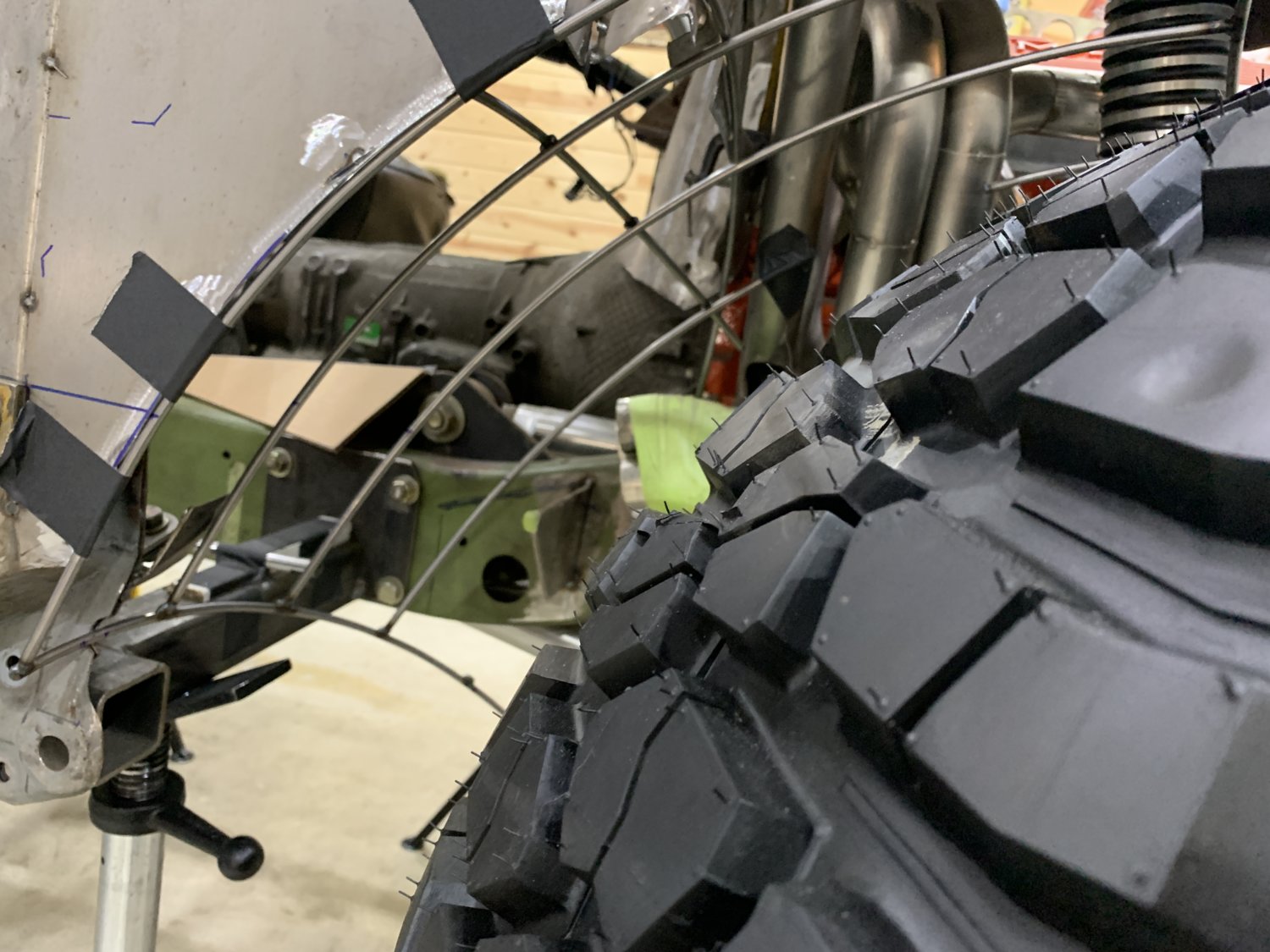
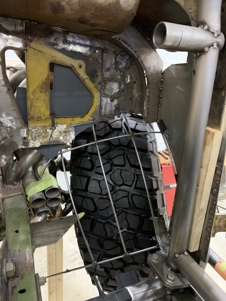
This was actually not THAT much of a surprise. They were built a little long deliberately so that they would provide maximum protection along the side. At normal ride height, they look like there's miles of clearance but from previous tests with the wide-swinging portal boxes the expectation was that some trimming would be needed to "fine tune" the length. As it turned out, removing 1" of DOM was all that was needed and then the knuckles were able to rotate all the way around to their steering stops. This basically puts the top of the tire completely inside the passenger footwell which doesn't show all that well in photos, but is crazy-looking when you see it in person.
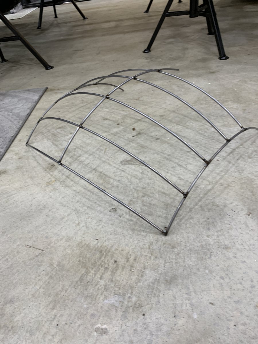
You can kind of get a sense of it here...
....and here.
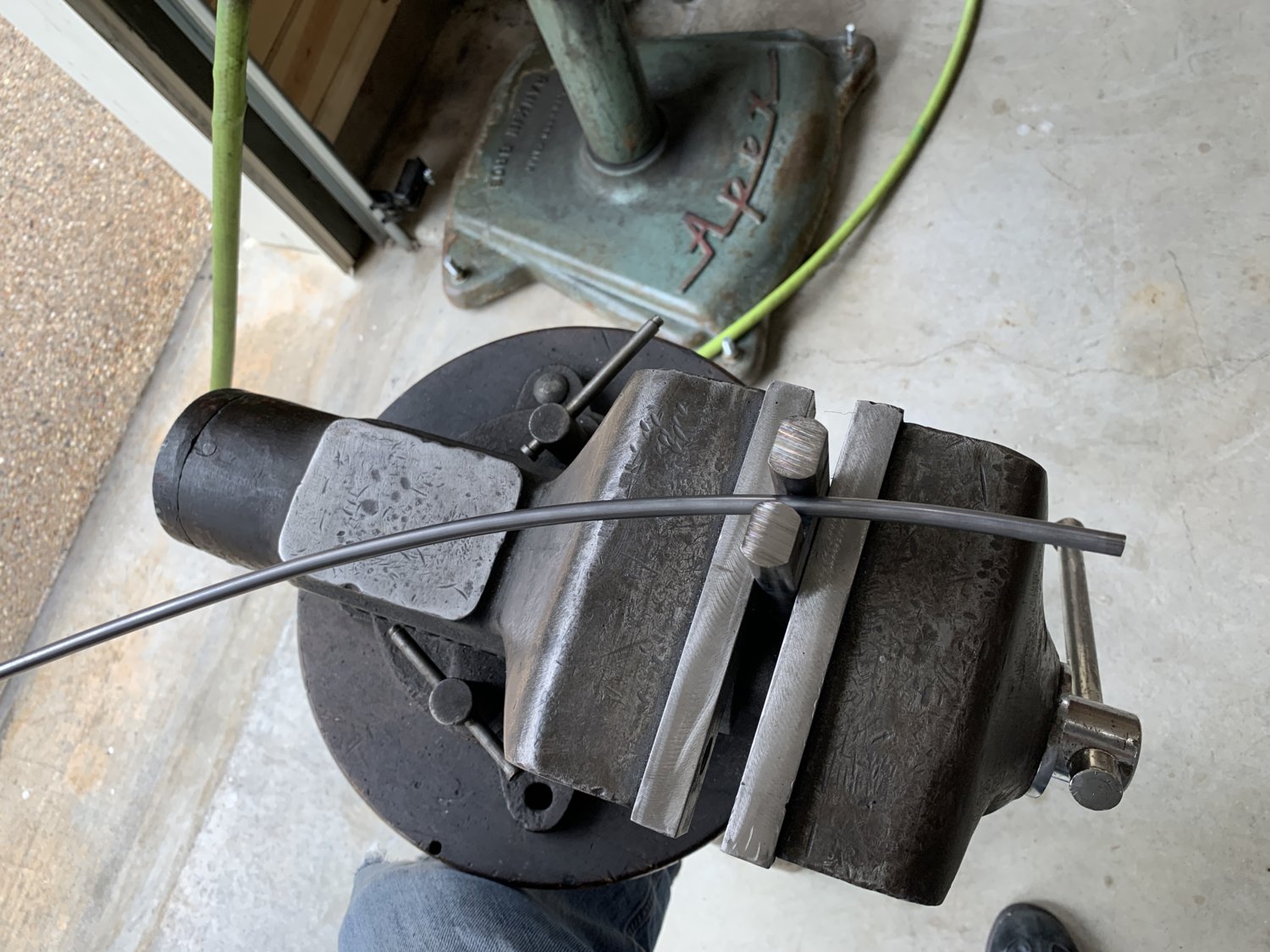
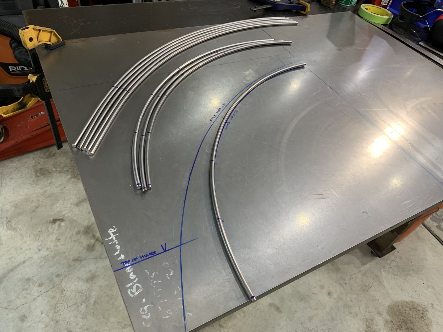
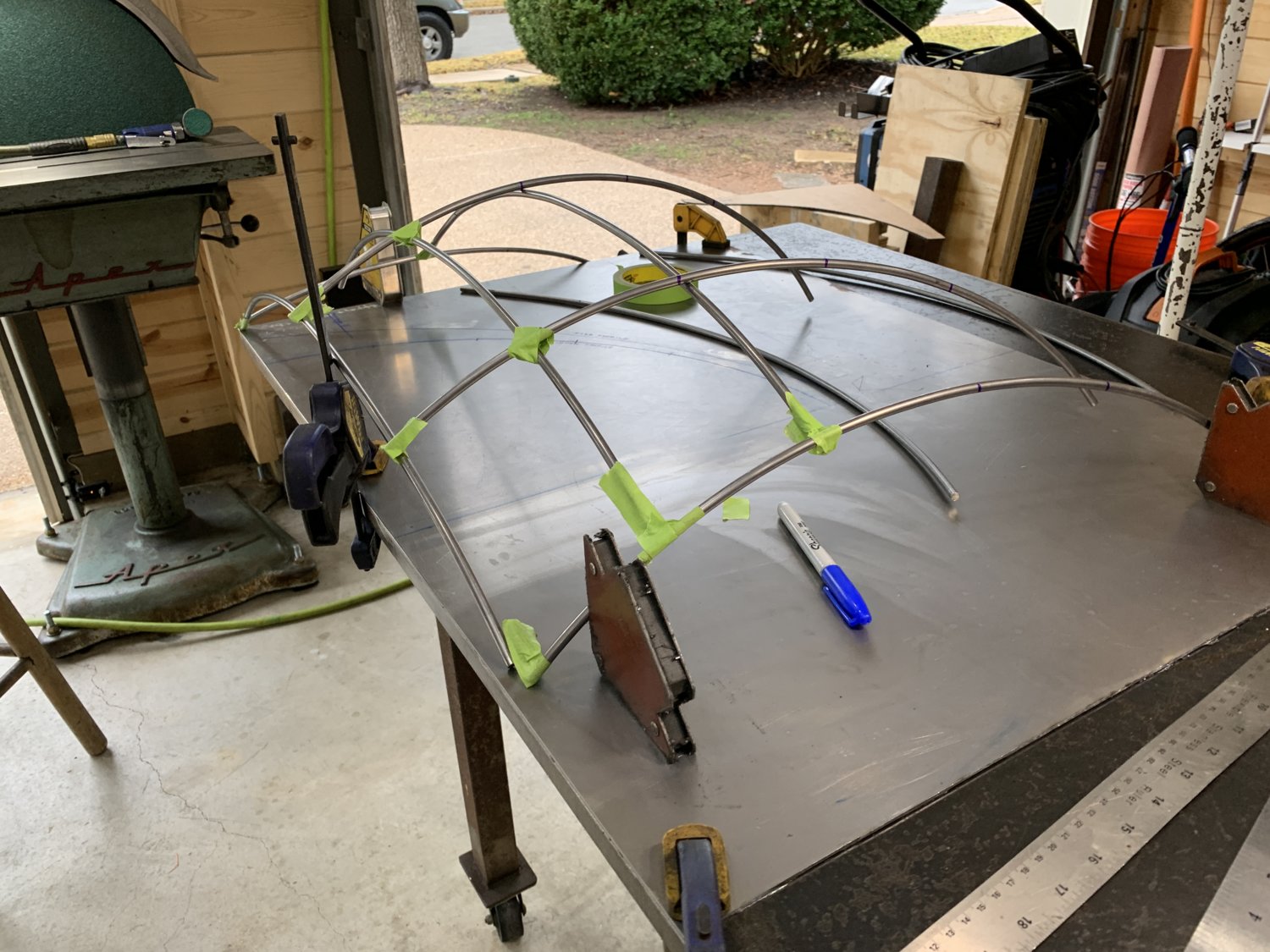
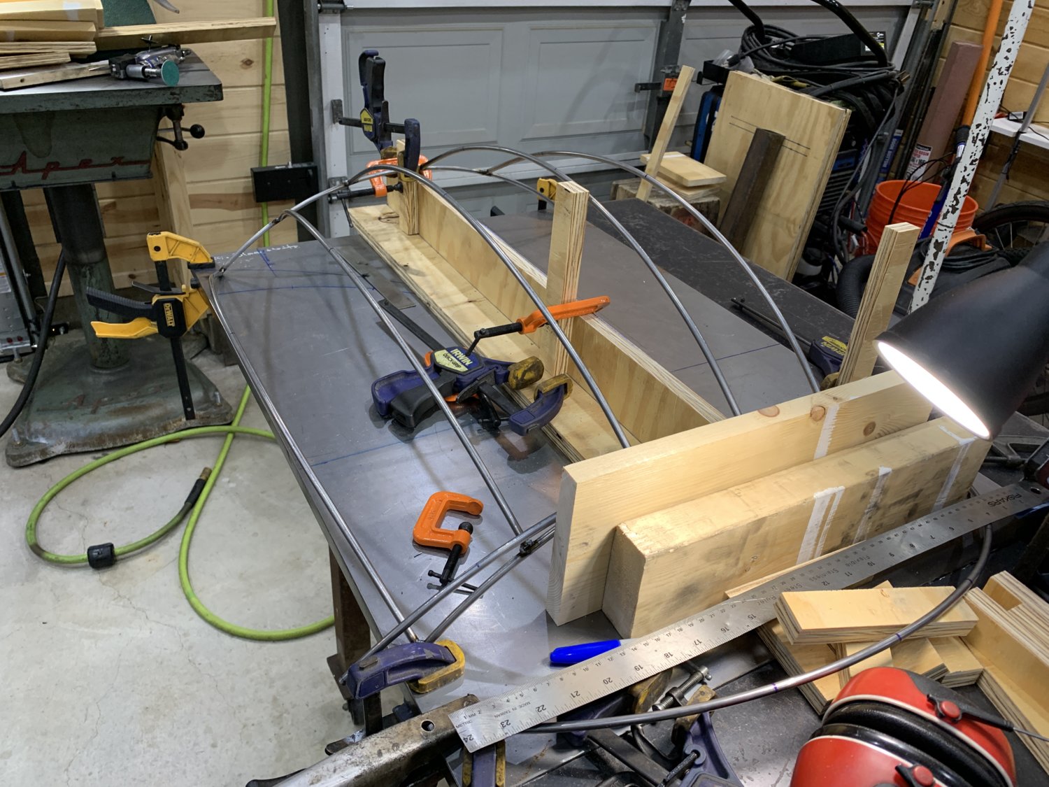
So, the rest of the day was spent trying to fabricate a new inner fenderwell that would not interfere with this crazy tire location but would also have a nice curve to it and provide much needed practice on the English Wheel. The hardest part of this sub-project is that (as you can see in that final photo) there is really almost nothing left of the firewall or floor to serve as an "index" to pull measurements from and most of what IS there is so sloppy and patchworked, that it's going to be cut out and replaced with new metal in the coming weeks too.
As with most MAW projects, the first side will probably take several hours and revisions and then once it's looking good it should only take a small fraction of that time to create the mirror-image version of that wheelwell for the driver's side. Then, it will be time to start laying down some new floors (with beadrolled details for strength!) and then probably a long fresh firewall panel and transmission tunnel.
It's a whole new set of disciplines to learn, so there is sure to be a good amount of "tuition pile" material stacked up in the corner, but really looking forward to the challenges and experiences of training myself on these new tools and processes.
-G
It took more than a month, but the Christmas present for the MAW build finally arrived today from Mittler Brothers.
The English Wheel was a great addition to the shop and the capabilities for working sheetmetal, but the piece that I'd really been looking forward to finally arrived today.
It's a bit larger than expected, but with the table folded down, it should tuck-away into a corner reasonably well. But for now, let's just keep it out in the middle of the floor and have a little playtime!!
As usual, instead of using a thin-gauge steel to get familiar with it... we went straight for it's maximum (16 GA, .060") since that what was handy. It's also the hardest to work with but ultimately the machine still handled it fine.
First impressions of beadrolling..... It's harder than it looks, you need REALLY good lighting near the dies to see exactly where the touchpoint is so that you can make your turns accurately, and swinging the metal around a sharp radius turn is going to take a lot more practice (and a slower pedal speed in those corners). Totally fun machine though and I can't wait to experiment with each of the die sets to get more familiar with all of them.
The other big initiative was to use the new 49" tall jackstands to finally get the truck ALL the way up in the air and cycle the front suspension in ways that were not possible in the NH garage due to the low ceiling rafters. The main objective was to confirm that there were no interferences at full bump / full droop with the wheels & tires installed AND also check the full- lock steering at the same time. After a lot of effort and adjustments of the jackstands, the photo that had never been possible before was finally captured late Sunday night.... You can see that there is just a small amount of daylight under the drooping driver's side tire and that ORI strut is 100% maxed-out for travel.
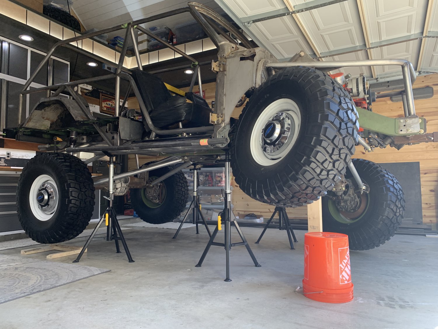
That was a pretty exciting victory and set everything up nicely for this morning. With better lighting, it was compulsory to get a least a few more beauty shots before starting the "full-lock steering" tests... The nitrogen had to be released from the passenger side strut to allow this articulation....otherwise it just kept wanting to lift up off the jackstands. (NOTE: The 2x4 in this photo is only supporting the weight of the axle housing and the wheel/tire.)
Of course, it wouldn't be a proper build day in the MAW shop without some kind of weird setback.... and today would be no different. When it came time to start checking steering clearances there was some kind of interference almost immediately with only a few degrees of rotation of the steering wheel. It was something really SOLID and immovable and it didn't take long to look around and find it.
The brand-new rocksliders!!
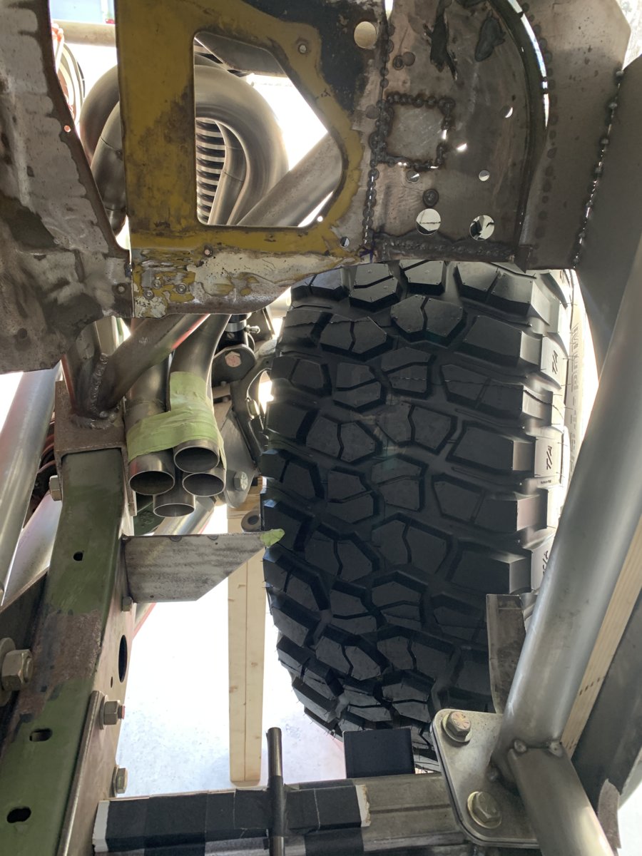
This was actually not THAT much of a surprise. They were built a little long deliberately so that they would provide maximum protection along the side. At normal ride height, they look like there's miles of clearance but from previous tests with the wide-swinging portal boxes the expectation was that some trimming would be needed to "fine tune" the length. As it turned out, removing 1" of DOM was all that was needed and then the knuckles were able to rotate all the way around to their steering stops. This basically puts the top of the tire completely inside the passenger footwell which doesn't show all that well in photos, but is crazy-looking when you see it in person.
You can kind of get a sense of it here...
....and here.
So, the rest of the day was spent trying to fabricate a new inner fenderwell that would not interfere with this crazy tire location but would also have a nice curve to it and provide much needed practice on the English Wheel. The hardest part of this sub-project is that (as you can see in that final photo) there is really almost nothing left of the firewall or floor to serve as an "index" to pull measurements from and most of what IS there is so sloppy and patchworked, that it's going to be cut out and replaced with new metal in the coming weeks too.
As with most MAW projects, the first side will probably take several hours and revisions and then once it's looking good it should only take a small fraction of that time to create the mirror-image version of that wheelwell for the driver's side. Then, it will be time to start laying down some new floors (with beadrolled details for strength!) and then probably a long fresh firewall panel and transmission tunnel.
It's a whole new set of disciplines to learn, so there is sure to be a good amount of "tuition pile" material stacked up in the corner, but really looking forward to the challenges and experiences of training myself on these new tools and processes.
-G


")