CK5
Register an account today to become a member! Once signed in, you'll be able to participate on this site by adding your own topics and posts, as well as connect with other members.
I think you're right. If that was even just a 1/4" radius (or slightly more) it would reduce the apparent size of that flare. It is amazing that small changes like that WILL have a noticeable effect. The fine-tuning will improve a lot of what is still wrong with this first prototype.

The stock fender arch is also not 100% circular in the upper hemisphere either. The side on the corner marker side goes slightly oval, and then actually curls back toward the "fang" area to close up the curve on that side...

The flare definitely helped a TON with keeping the overall wheel opening smaller. It's was an easy tradeoff to make.


-G

So tires still turns lock to lock ok? Is that tire position worst case scenario (looks like it is)?
 
So tires still turns lock to lock ok? Is that tire position worst case scenario (looks like it is)?

That's as bad as it gets... all the interferences are on the sides, there is loads of room at the top of the arch. I could lower it but would lose the overall proportions of a factory opening.

The sides can be brought in tighter to close up the shape, but the flare has to increase at the same time to allow the tire to "tuck behind" the opening as it swings....

Doing that gets "odd" down below that lower style line on the fender because that is where the factory flare ends. If I get aggressive and try to incorporate a flare down into that area, I can make the overall arch narrower... but it's not clear to me how to deal with that awkward area down near the bottom.


-G
I guess it somewhat depends on how your going to connect the current fender with the flare? Seamless joint between flare and fender welded in would be my guess?
 
I guess it somewhat depends on how your going to connect the current fender with the flare? Seamless joint between flare and fender welded in would be my guess?
Once I get a good shape rendered in metal, it will probably get Cleco'ed to the fender and then carefully cut/trimmed so that it can be butt-welded into place.

There really isn't any concern about clearance once the tire tucks under the new lip area. If it clears on the outer edge of that fenderlip curve, it's golden everywhere as the tire continues rotating to full-lock.


Right about now, I'd really like to have one of those $50,000 portable 3D hand-scanners in my shop. It would be awesome to just take the pattern I've created... scan it... then mess around with it on CAD to stretch and modify the curves, and experiment with all sorts of subtle visual changes to the wheel arch. Turns out, you can buy a LOT of gaffer tape for that same $50K..... maybe even only $10K.. Though the stuff is actually kind of expensive as far as tape is concerned. LOL


-G
 
The arch has a really nice high line. It will look right and proportional to the tires at ride height.

David
 
The arch has a really nice high line. It will look right and proportional to the tires at ride height.

David

I think you are probably right... and I have been deliberately avoiding messing with the arch for a couple of days. Sometimes it's tempting to just keep revising and revising endlessly.... the results will be "different" but not necessarily any "better".

Really don't want to take the truck off the tall jackstands yet, but might be able to set the axle at "ride height" by putting it on a bunch of cribbing/blocking to also see this design at a normal (non-articulated) stance.


-G
 
If you think THAT update was imaginative, just wait for the YouTube video of me sitting in the driver's seat making VROOOM VROOM noises and pretending that this truck actually runs!!!


-G
You aren't that far off from actually getting it running if you decide to have a running engine in the chassis.....:pimp:
 
You aren't that far off from actually getting it running if you decide to have a running engine in the chassis.....:pimp:

Hmmm..... yeah that's true.

You'd think with all the money you coaxed me into spending over the last couple of years (Brodix aluminum heads, new custom-grind cam, etc.) I'd be in more of a hurry to get that engine fired up....

Need to finish welding / baffling / mounting the fuel tank.... running the supply and return lines and finish welding the headers and collectors... and entire length of exhaust actually.
Then decide if going with a distributorless ignition (Crankfire controlled by the Terminator ECU) is another "Might As Well" that needs to be purchased.....

Kind of got off on a small metalworking tangent lately after getting the seat mounts completed, but really..... I need to get back soon to running fuel, brake and air lines along the framerails before I install the new floors and make access a lot harder for myself.


-G
 
The sheetmetal work is pretty cool too, its all cool. Those fender flares are lookin' spiffy!
 
Have you moved the wheel down to see how the fender looks at ride height?
No.... we were talking about that a little while back. It's a good sanity check for sure.

Here is the "original" fender mod that attempted to follow the profile of a stock 1st Gen fender...
You can see that it's more asymetrical at the top of the curve (toward the headlight area) and almost curls back under as it get down to the fang area.
On the trailing edge its really quite straight, especially below the style line at the bottom.

full


For fun, I printed out this photo at the same size as the new design and laid it on top for comparison. It was remarkably close except that the top of the fenderlip is about 1.5" taller with the old design. The sides and overall width is virtually identical.
For "V2", I will probably try to match this original shape more closely, but still give it the 2.5" flare. We'll see how that looks next. Maybe I should just buy more fenders so I don't have to destroy my last one? :thinking:

-G
 
2021.03.08 - UPDATE - CLECO SUNDAY...!!!


Made some decent progress yesterday.

Played with the new cordless shear again as I created 2 new tuition pile firewalls.... but 3 times is a charm! Also did a little TIG'ing on mild steel (a first for me).... and finally got to use the Clecos that were purchased several years ago and were sitting in the toolbox drawer all this time.

Those things are super cool, and make panel fitting a real pleasure.

Here are a couple shot of the wheel arch mated to firewall #3.... (with the old firewall cut out on the passenger side)

full


Also, joined the stretched center section over to the new firewall sheetmetal with more Clecos.... and started playing around with white cardstock to create floor templates as well.

full


It coming together... never as quickly as hoped, but it's good progress.


-G
 
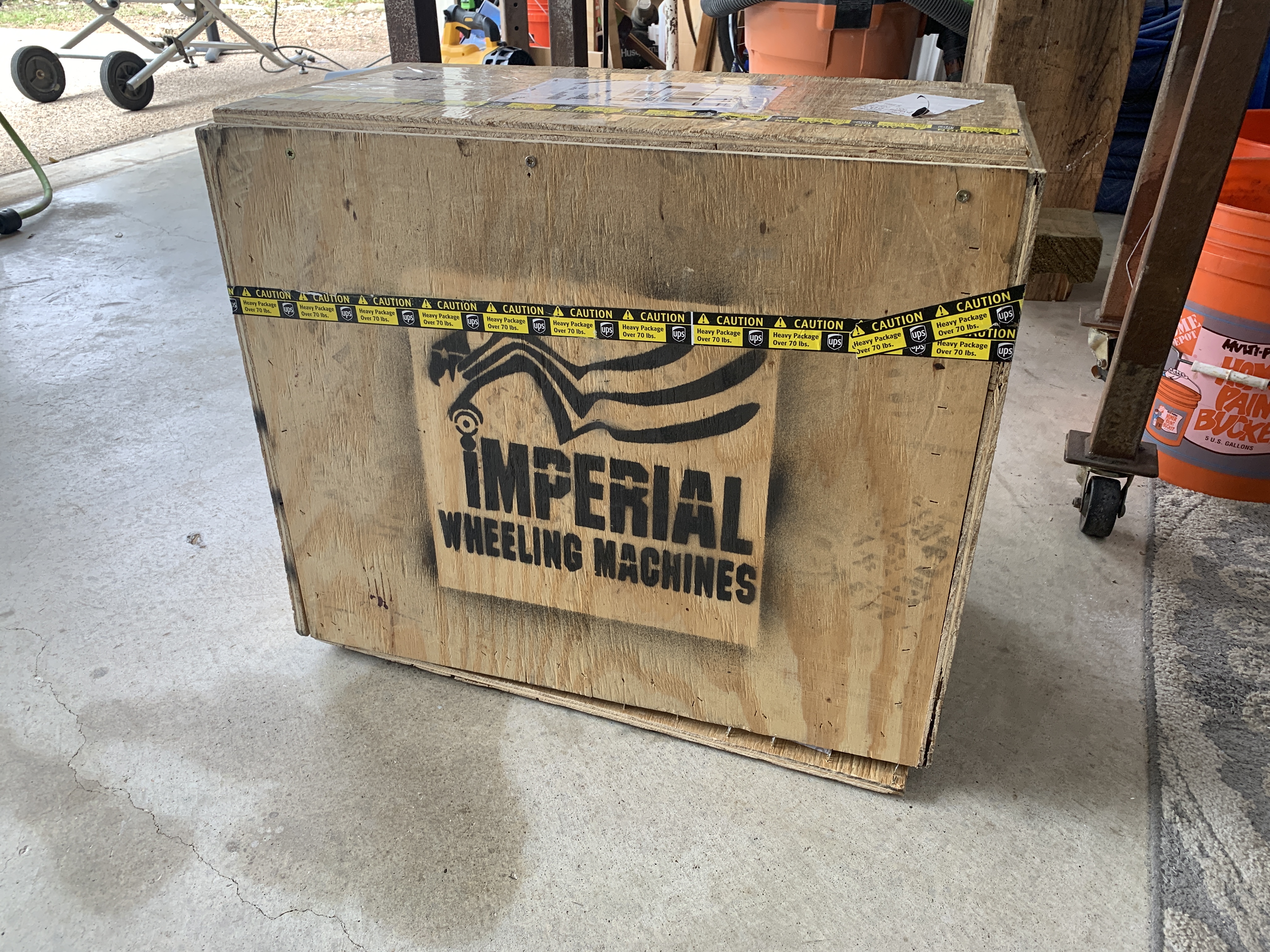
2021.03.22 - UPDATE! - THE LAST TOOL!!!

It's been a few weeks since the backorder was placed, but the new (and perhaps final?) tool for metalworking projects has finally arrived!!

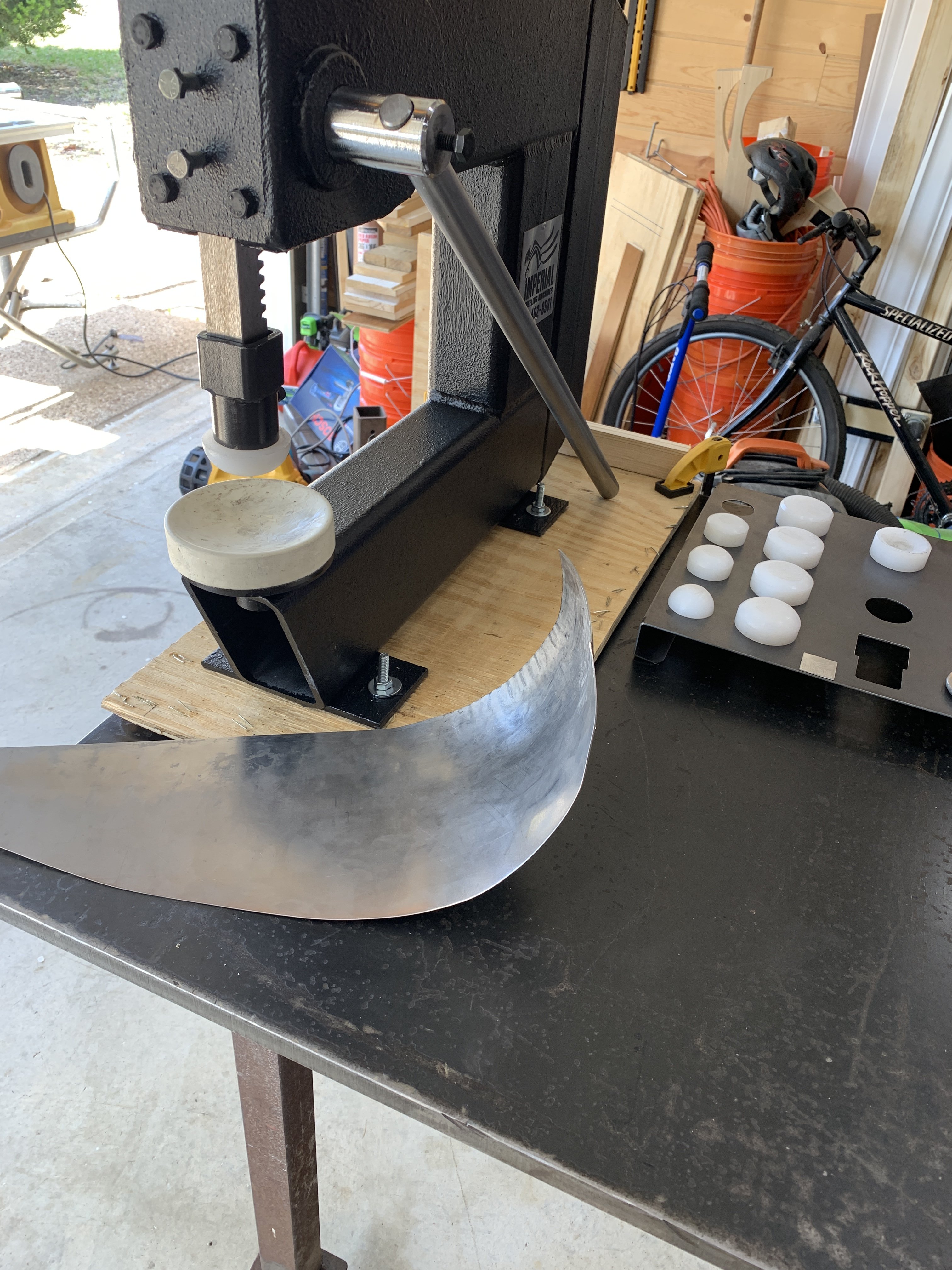
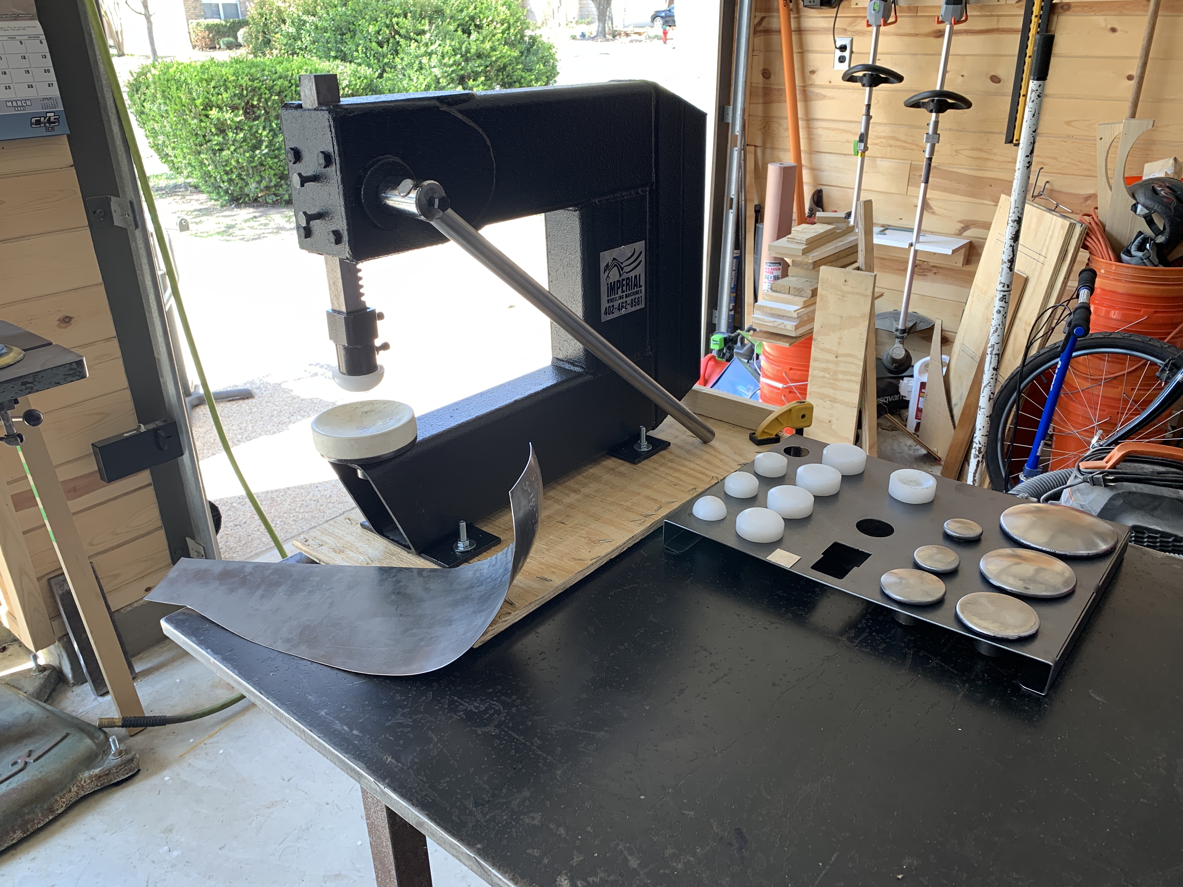
The Imperial Wheeling Machines fabricated arbor press.... this thing RULES!!!
The die set consists of a huge array of upper dies in various shapes and profiles, and a large lower cup made out of a really stiff rubber to crush the metal against. This replaces the traditional hammer & stump (or shotbag) part of metalforming with a much faster and quieter alternative.

full


For starters, I just put in one of the high-crown polyurethane upper dies and grabbed a scrap piece of metal to play around with. Starting maybe 2" in from the edge, just starting pulling down the handle and immediately got nice "taco shaped" wrinkles in the metal along one side.... Then, on a second pass just passed those high spots under the die, and crushed them down and gathered-up the metal perfectly, creating a really high-crown result in just a matter of minutes.

full


This kind of shape in 16GA would have taken me literally HOURS worth of hammering, sore arms and shoulders and noise that would have the neighbors calling my HOA!!!! Now it's possible to get a panel into a rough shape in maybe 15 minutes, and then another 15 minutes on the English Wheel to smooth-out the walnut dents. Can't wait to start on the driver's side footwell panel to see what sort of result I can get, and to compare the total time required vs. the 20 hours I spent on the first one.

full


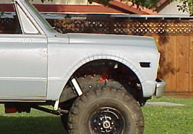
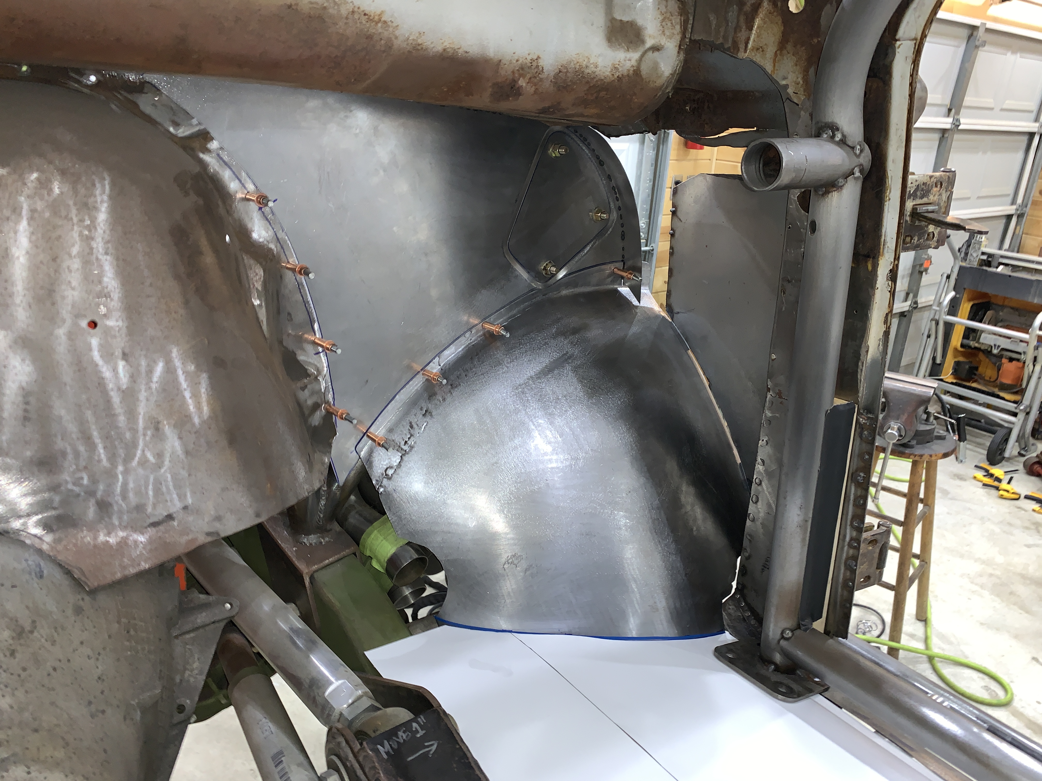
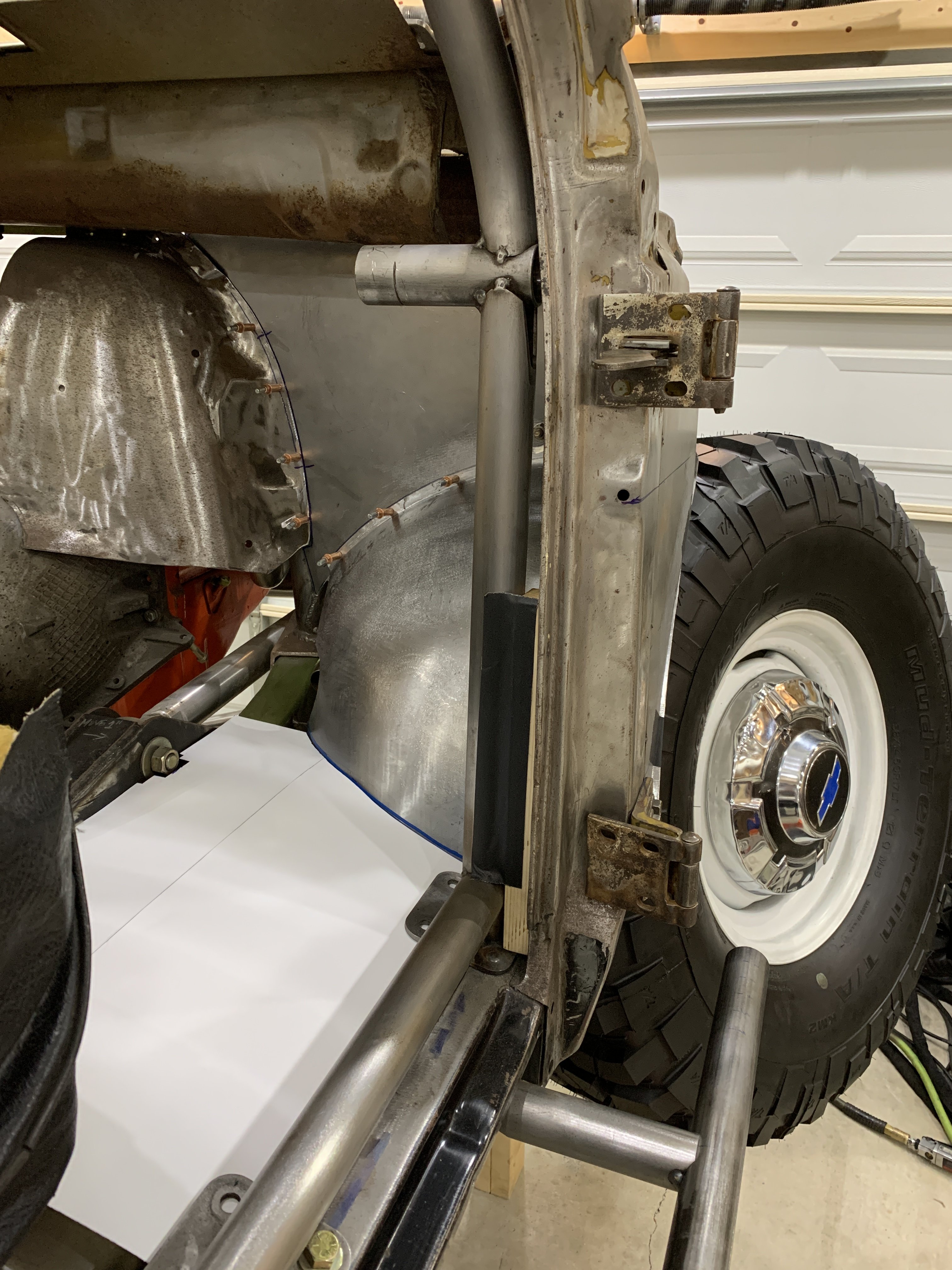
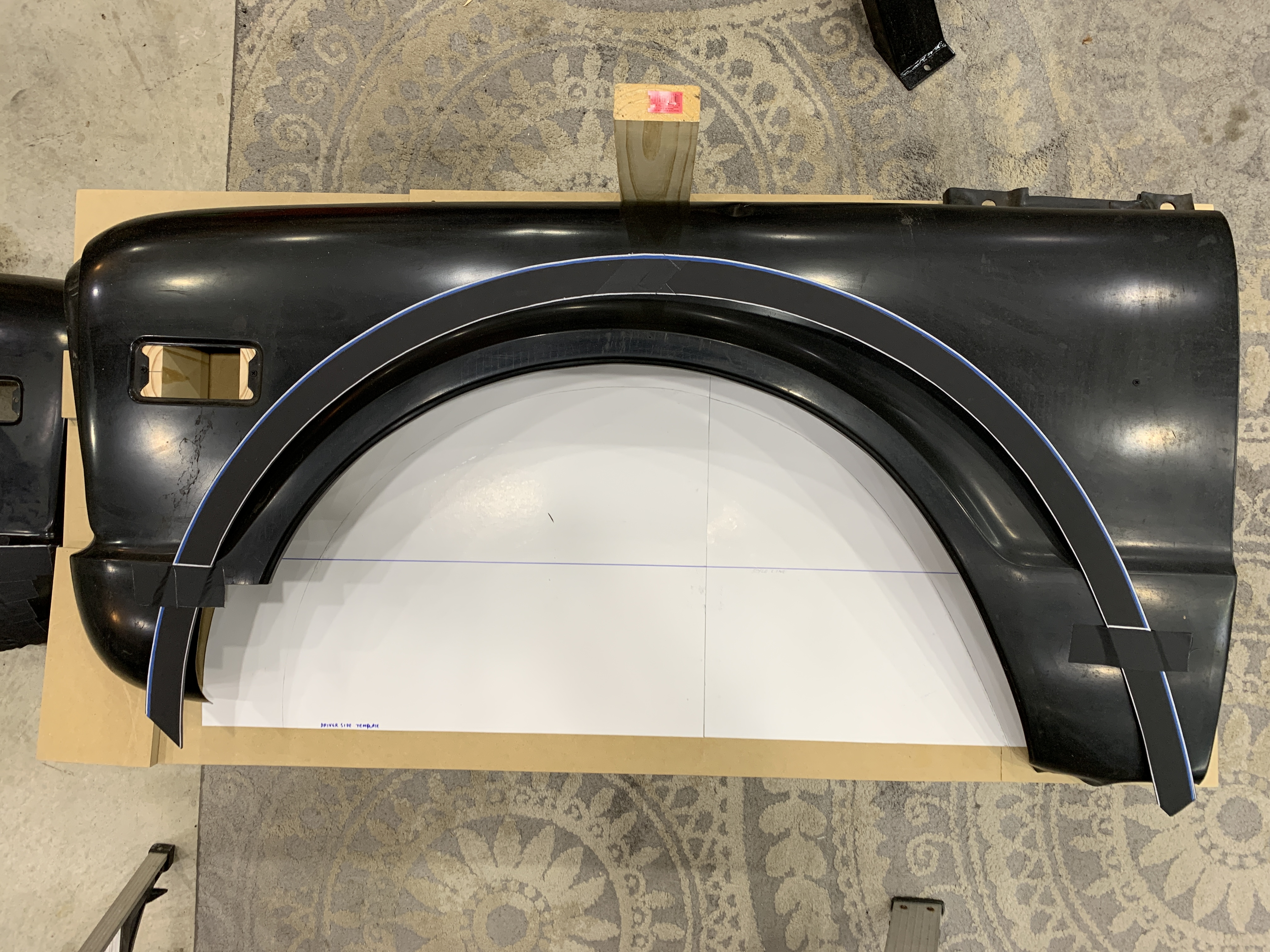
Spent most of the day yesterday building a new front fender fixture starting with a 30" x 60" sheet of 3/4" thick MDF. The 1st Gen fenders are really easy to fixture up because of the pre-existing holes for the front marker light and the rear two holes for the "K5 Blazer" emblem. Built standoffs for each of those to hold the fender in nice "neutral" position, and drywall screws turn out to be the perfect size to secure the fender using those predrilled holes.

full


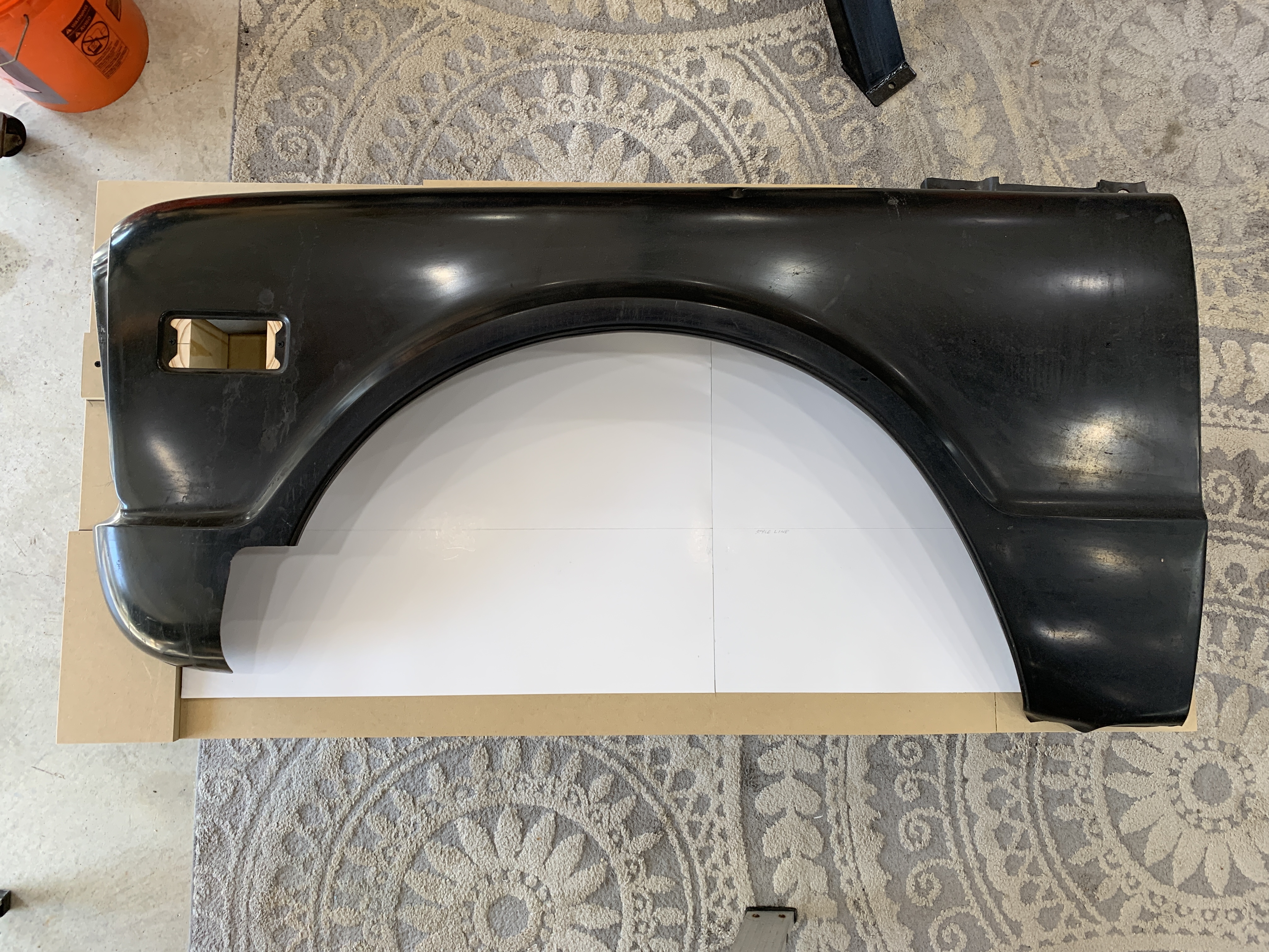
With the fender in position, some white heavy cardstock was slid in underneath and the factory fender curve was transferred down to the paper from above. From there it was a simple matter to remove that paper and then mark out a larger opening... scaling up the original profile a few inches larger all the way around. This will allow for a "Version 2" mock up of the fender with a more correct curvature, and if it looks the way I'm hoping then I can start using these paper templates to start cutting out actual metal fender arches and start working on building the fenders out of steel in the coming weeks.


-G
 
Kinda curious if you could keep the inner part of the fender (with the hood mount) and just “replace” the outer skin with your new version? Thinking through that seems like it’d be more work but I remember old plans were the fenders would be removable so maybe don’t need the stock mounting holes?
 
Kinda curious if you could keep the inner part of the fender (with the hood mount) and just “replace” the outer skin with your new version? Thinking through that seems like it’d be more work but I remember old plans were the fenders would be removable so maybe don’t need the stock mounting holes?

Yeah, I'm pretty much done with the idea of removable fenders / hood / grille at this point.

There has been so much scope-creep with this project since it started that if I tried to implement everything that was originally dreamt-up for this project, I'd still have another 10 years of building ahead of me.

The removable fender idea was interesting, but ultimately was low-priority relative to some of the other stuff I wanted to do (portals, links, CTIS, etc.)....

I don't want to jinx myself, but my day job workload seems to finally be getting back to a more normal workweek... and I'm hoping that translates to more free time in the shop with all of these new tools.


-G
 
I don't want to jinx myself, but my day job workload seems to finally be getting back to a more normal workweek... and I'm hoping that translates to more free time in the shop and all of these new tools.


-G
That's great to hear!
 
2021.03.22 - UPDATE! - NEW FENDER ARCH..!!!


So.... here is "V2" of the front fender arch design.... :waytogo:

full


This one was pulled directly off the stock fender arch profile and then scaled-up to give the necessary clearance. The notable improvements are the leading edge of the curve which now is much more curved all the way to the fang area... and the trailing edge of the fender becomes "almost" straight below the style line (there is maybe 1/8" of curve from the style line to the bottom of the fender.... it's a really subtle but important aesthetic detail)

Based on "V1"... the offset relative to the stock opening is basically correct here. The bias is definitely more rearward for the tire clearance that is actually needed. The nice part of that is that it keeps the flare out of the front turn signal indicator area, so that does not have to be relocated.

Looks like it's getting much closer to a nice final design, and it's probably time to go buy a large sheet of 20GA so that this pattern can be transferred to steel for mock up tests. Of course, since I started on the passenger side fender, all that 's needed is to just flip this template over for the mirror-image pattern.


-G
 
Top Bottom