
here it is out.... definitely "in the way", maybe a bit awkward looking too....
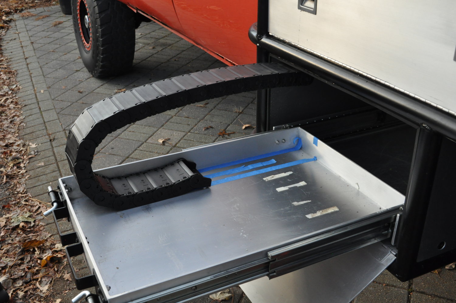
the lip and light mean it would have to be "padded" down off the ceiling to clear it.... that isn't horrible as i have to pad it on top or bottom, or a combo of both to add another inch to the loop height.... the next larger size is too tall...
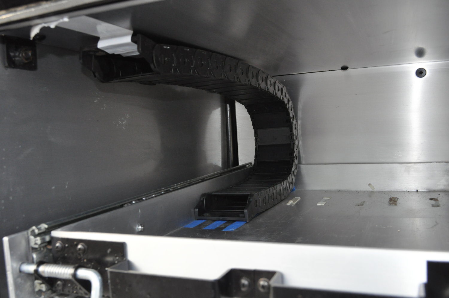
the space is about 10 1/4" high.. the loop height is 9 1/4"... it would work, but you'll see in this second pic, it adds track sag... if i can make the space the actual loop height, the track will stay flush on the ceiling, and tray as it operates....
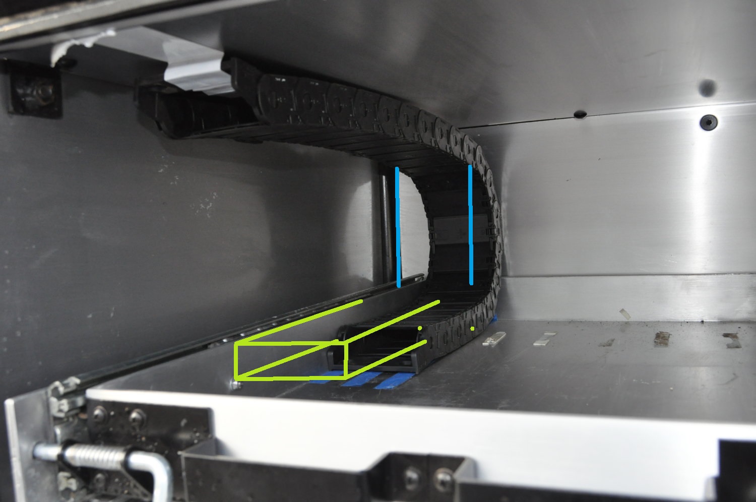
this is about how it will look.. tho it will be back a tad on entry/exit as it will move tighter against the back wall as the loop height is corrected.... you can also see the sag here, even just taped....
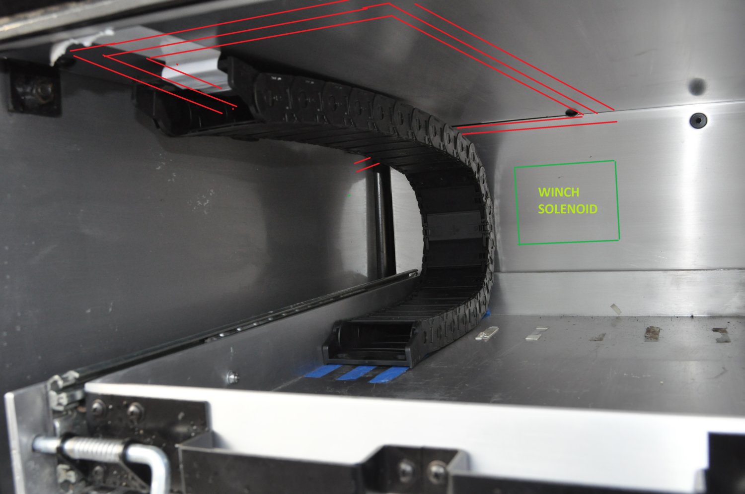
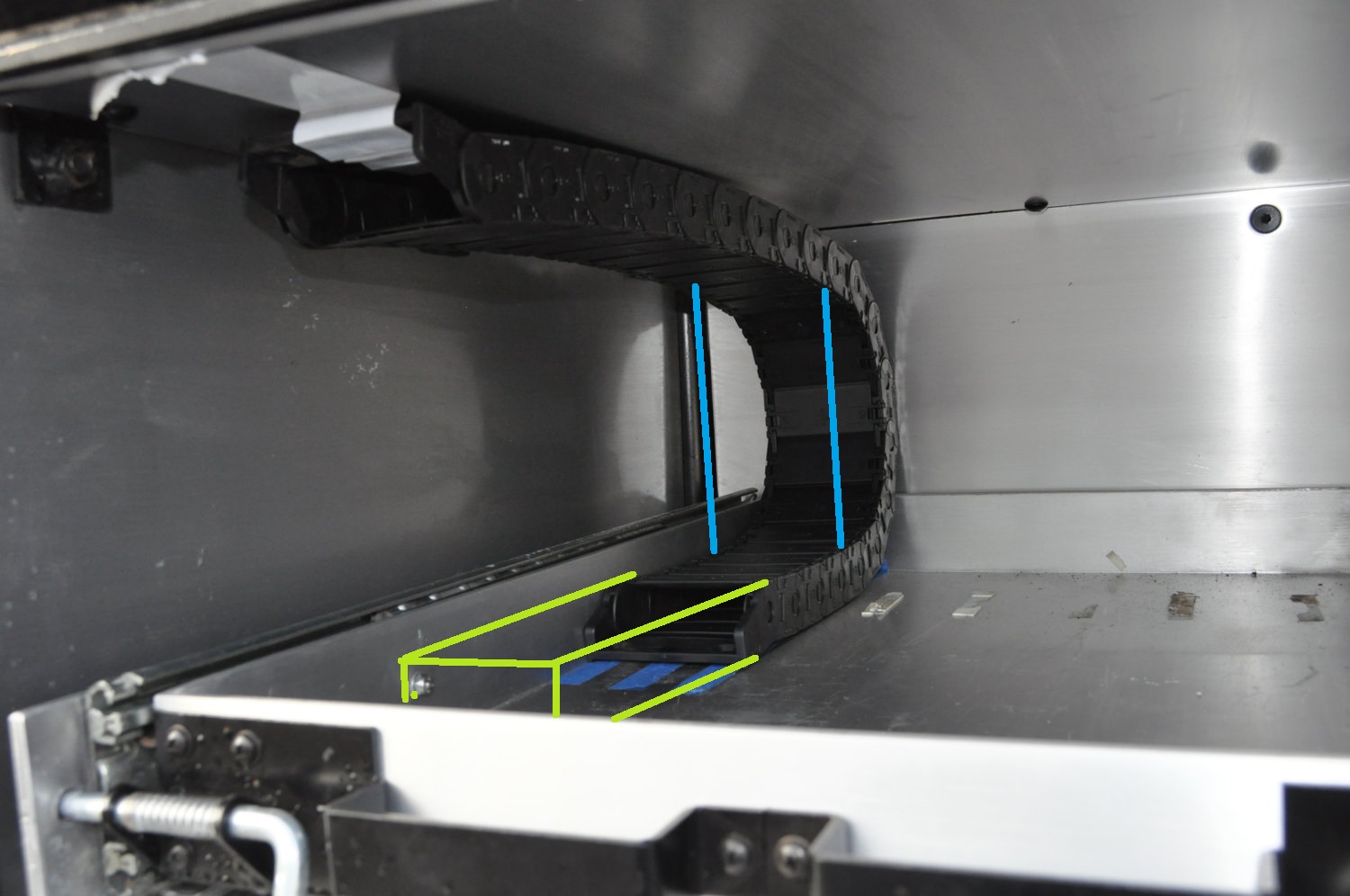
i'm gonna pad the tray up an inch when i add the inner wall, etc... i'd rather the wires exit an inch up in the tray, than an inch down off the ceiling.... need to actually cut the wall to show ya an "open" shot....
the lip and light mean it would have to be "padded" down off the ceiling to clear it.... that isn't horrible as i have to pad it on top or bottom, or a combo of both to add another inch to the loop height.... the next larger size is too tall...
the space is about 10 1/4" high.. the loop height is 9 1/4"... it would work, but you'll see in this second pic, it adds track sag... if i can make the space the actual loop height, the track will stay flush on the ceiling, and tray as it operates....
this is about how it will look.. tho it will be back a tad on entry/exit as it will move tighter against the back wall as the loop height is corrected.... you can also see the sag here, even just taped....
i'm gonna pad the tray up an inch when i add the inner wall, etc... i'd rather the wires exit an inch up in the tray, than an inch down off the ceiling.... need to actually cut the wall to show ya an "open" shot....
")


 but, ya know, it's like a sledge smackin ya in the back of your hotrod soul, that needs some itchin.....


